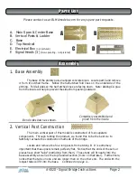
A. Main Span & Center Base
B. Vertical Posts & Ladder
C. Base
D. Top Handrail
E. Electrical Box
(not pictured)
F. Signal Heads (3)
(Non-operating - not pictured)
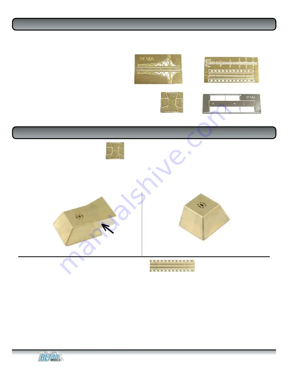
1. Base Assembly
The base of the prototype is an angled concrete block. Locate part C and remove
it from it’s etched frame. Notice the half-etched fold lines on the underside of the
etching. Fold all sides so the half-etched lines are facing down. Note: Adding CA glue
from the inside will help to prevent the sides from pushing outward.
Please contact us at BLMAmodels.com for any spare part requests.
A
B
D
C
Bend sides down as shown.
Completely assembled and
glued from the inside.
2. Vertical Post Construction
The main vertical post of this model is constructed of four separate
components. Through testing the product, we found this to be the best we to
faithfully recreate the construction methods of the bridge.
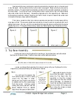
Locate and remove the four long posts from etching B. It is extremely
important that these posts remain perfectly flat. Notice that the ends of these four
pieces have short “tabs” protruding from them. These tabs will fit neatly into the
base assembly as well as the top handrail section (more on that later). Furthermore,
notice that the tabs on one end are longer than on the other end. The end with the
longest tabs will fit into the base.
Continued on page 3...
Assembly
Assembly
Parts List
Parts List
#4020 - Signal Bridge Instructions Page 2


