background image

大型风扇行业的领航者


if head room is a problem-as long as there is adequate“breathing room” above the fan.


But, be advised that sometimes a fan would run with almost no sway when hung from our 

free swiveling mount, will sway radically when bolted directly to a lightweight beam of 

commonly found in steel building. This is because a slight imbalance can, at a certain


rpm, excite the natural frequency of the beam in torsion, thereby amplifying the sway. Also,
without the free swiveling mount, more noise is telegraphed back to the building structure.

4.3


Installation of the drive device

(1)

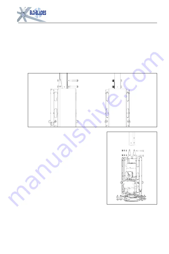
The  drive  device  has  been  installed  into  a  unit  before  shipping  out,  only  fix  it  to  the


extension rod by using bolts, as shown in figure 4.3.


(2)D

ue to the drive device weight, 2-3 people are


needed to install. If there is a scissors lift, you can use the


lift  to assist in  assembly,  the  hoisting  weight  of the  lifting


equipment shall not be less than 440lbs, the hoisting


process must be slow, even, and at the same time it needs


someone to hold the drive device, to prevent oscillation.

(3)

Do not remove oil plug until fan is properly mounted. If


the oil plug is removed before the fan is mounted, oil in the 

gear reducer may spill out.

4.4


Run the conduit and install wiring,

(1)


along the facility structure, along the top of the beam layout, per code.

15

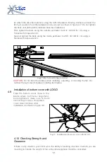
Fig4.3


Installation of the driving unit

Summary of Contents for OM-KQ-4E

Page 1: ... 5 Electrical installation 19 21 6 Guy Cabling BloBlades 22 23 7 Start up procedure 23 24 8 Cleaning And User Maintenance 24 25 9 General trouble shooting 26 10 Letter of Warranty 27 11 Limitation of warranty and liability 28 29 Blo Blades LLC 1310 E Cornwallis Rd Durham NC 27713 PH 833 Blo Fans Email info bloblades com Blo Blades Contents ...

Page 2: ...ade Connector Airfoil Safety Retainer Plug In Bottom Cover Main Motor 1ea Universal Joint Assembly Structural Support of the building Typical I Beam 4ea M16 Nut Bolt 1ea Extension Bar Other Lengths Available 1ea Hoist Assembly 6ea Fan Blade Interconnection Safety Assemblies 1ea Fan Cover 6ea Fan Blades ...

Page 3: ...resents the number one and leading manufacturer of HVLS Fans for large industrial fans with large coverage and in all directions For many decades there has been focus on only one thing HVLS Big Fans development and innovation which are widely use in large warehouses distribution centers manufacturing facilities and commercial buildings with high ceilings to deliver maximum airflow Our fans are not...

Page 4: ...90L 4 coaxial helical gear reducer Output shaft uses the SKF VL taped roller bearing Shell Omala VG680 synthetic gear oil has 20 000 hours of free maintenance The output shaft uses Freudenberg Simrithigh temperature double lipped output oil seal Gear Box automatic exhaust valve New generation energy efficient level 4 motor with NEMA IE2 Standards 220V 480V 60HZ IP55 F IM M4 4 I Power 1 5kw 50 60 H...

Page 5: ...rning labels are printed in control box 3Ph 480V 60Hz or 1Ph 220V 60hz are available for power supply 1 3 6 Safety System Components BloBlades Open fans are engineered with key safety features to prevent pieces of the fan from falling in the unlikely event of a catastrophic failure Used together these systems and devices provide comprehensive protection of people equipment and property Follow the ...

Page 6: ...controllers contain high voltage capacitors which take time to discharge after removal of mains supply Before working on the fan controller ensure isolation of main supply from line inputs at Safety links should be connected each blade and to the adjacent blades and reinforce the area between the mounting holes this precautionary measure will help prevent a blade from falling should one break off ...

Page 7: ...e BloBlades supplied controllers which are suitable with this model Other parts or controllers cannot be substituted CAUTION When service or replacement of a component in the fan requires the removal or disconnection of a safety device the safety device is to be reinstalled or remounted as previously installed 2 3 WARNING TO REDUCE THE RISK OF FIRE ELECTRIC SHOCK OR INJURY TO PERSONS OBSERVE THE F...

Page 8: ...o support the load prior to fan installation 2 Take measurements of the height of the bottom of I beam and blade level 3 Check if you have the correct power circuit for the fan 3 2 General Mounting Considerations CAUTION Bloblades Fans product warranty will not cover equipment damage or failure that is caused by improper installation 3 2 1 Weight A standard six blade 24 fan which is the biggest fa...

Page 9: ... is adequate to withstand 220 N m 3 2 3 Safety Cable Because of the obvious risk of a falling fan whatever mounting method is used to suspend the fan it should always be backed up with a safety cable Safety cable along with all required hardware is supplied with every fan An HVLS fan should never be run without a properly installed safety cable Refer to fig 3 1 for proper installation of safety ca...

Page 10: ...it This means that a fan should never be mounted lower than 10 above the floor Similarly if there is a mezzanine section in the facility it is important that a fan not be placed so close to the mezzanine that a person on an upper tier could reach out and contact the fan Wherever there is a potential for a forklift to elevate something into the fan or people working with long material inadvertently...

Page 11: ...oving around a lot and a little windiness here and there is not a problem 24 long blade fans on 110 centers might be suffice 3 3 2 Vertical positioning In many applications physical limitations overhead cranes low ceilings etc dictate vertical positioning Where there is some latitude here are the primary points to consider From a strictly performance point of view 19 5 to 33 is the optimum height ...

Page 12: ...e fan can be easily clip on any steel I beam without the need to change any steel beam figure 4 1 2 Connection with concrete beam the standard device is fixed by expansion bolts on the concrete beam the device can be adjusted according to the width of the beam meetingthe demand of concrete beams with different dimensions 3 If your facility has another structure please call 833 BLO Blades for poten...

Page 13: ...nting hardware that comes with an BloBlade fan has a 300mm extension or drop and clamp designed for use on a steel I beam without modification to the beam fig 4 2 since beams are often sloped so the roof can shed water and not all roofs slope the same the mount is free swiveling This allows the fan to find its own level position no matter what the slope Fig4 2 Univisal Joint ...

Page 14: ...e drive device has been installed into a unit before shipping out only fix it to the extension rod by using bolts as shown in figure 4 3 2 Due to the drive device weight 2 3 people are needed to install If there is a scissors lift you can use the lift to assist in assembly the hoisting weight of the lifting equipment shall not be less than 440lbs the hoisting process must be slow even and at the s...

Page 15: ... circular uniform guy wires try to ensure that the angle between each gay wire and the drive device is 45 too big or too small will effect the guy wire The function of the guy wire is mainly the following 1 To reduce the fan shake when running 2 The guy wires ensure that the level of the fan improve the dynamic balance of the fan 3 The safety protection devices to prevent falling the fan 4 6 Insta...

Page 16: ...er to the fan before installing the airfoils 2 Slide the airfoils onto the tabs of the fan hub This is usually done after the motor hub assembly has been mounted and the guy cables have been installed The blades should slide on easily if not a little finesse works better than force Refer to fig 4 6 to make sure you are installing the blades facing the right way An airfoil will only attach to the f...

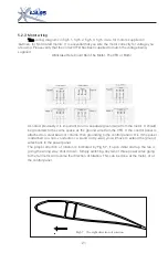
Page 17: ...TION Do not bend the blades when installing adjusting or cleaning the fan Do notinsert foreign objects between rotating fan blades Installation of bottom cover with LOGO Take the bottom cover close to the blade wheel bolt holes alignment bolts tightened make sure no bolts are missing or loose the bottom cover does not move after installation as shown in figure 4 8 Fig4 7Attach 6 safety ring to Air...

Page 18: ...aking sure safety cables are installed an easy way to test the mounting s ability to handle the torque is to insert a 3 5 long 2x4 in the motor frame and try to twist itas shown in fig 4 10 if the fan is hanging from an extension you will have to use one hand on the 2x4 and the other on the motor frame so as to create a torque without exerting a big side load The mount should withstand a 110lb for...

Page 19: ...lso amplify the voltages spikes 3 Put the wires to each fan in separate grounded metallic conduit Do not bundle them together with the power wires going into the control panel or with wires going to other fans Use a section of flex conduit between the building structure and the fan to accommodate fan movement 4 Be sure to pull 4 wires you need 3 for power and 1 for ground 5 Alternatively you can u...

Page 20: ... motor It should be grounded to the same space as the ground wire from the VFD If the control panel is attached to a steel beam or column then grounding to the control panel is Ok If the panel is attached to a non conductor i e wood or dry wall you will have to extend the ground wires back to the power panel The proper direction of rotation is indicated by Fig 5 7 if upon initial start up the fan ...

Page 21: ...s per cable i e two clamps per end c Don t angle the guy cables too steeply Anything much steeper than a 45 degree is not desirable Buy extra cable if you need it d Use eye bolts to attach the guy cables to the building structure and use the open end chain links supplied with hardware to attach the cables to the fan frame Note it is important to avoid wrapping the cable around the sharp corners Al...

Page 22: ...p the fan Note The key to insuring that cables stay tight is making sure the have fair amount of tension on them to begin with 4 Loosen the outermost clamp take up the slack and retighten the clamp so that both clamps are holding the tension Start up Procedure Turn switch to the ON position when power is applied the green On indicator located on the front of panel will light Adjust the speed contr...

Page 23: ...intenance inspection to your fan to ensure its safe and efficient operation If you have any questions please contact customer service at 833 BLO FANS Control Panel Occasional cleaning may be advisable especially when the panel is located in a dusty or dirty environment take out the air inlet and outlet filter use compressed air gun to blow off any buildup of foreign material from the VFD or coolin...

Page 24: ...a VG680 or recommend equivalent as specified on gear reducer manual Inspect motor terminations inside junction box and tighten if necessary 8 3 Blades Dirt on the blades will reduce airfoil efficiency Clean the blades whenever they are visibly dirty Use a detergent if necessary Ensure all bolts securing airfoils to fan are present and torque to 39N m Ensure airfoils are secured to one another by a...

Page 25: ...9 3 Fan is Not Starting Make sure that all wires are securely connected Make sure the 3 ways switch are in on position Verify the supply power is adequate and functional contact BloBlades 833 BLO FANS 9 4 Motor makes noise when you speed up the fan Audible high frequency noise is normal during fan operation if this is less than desirable or you feel that the noise maybe a result of mechanical fail...

Page 26: ...y purchaser Any other means of repair such as performing the repairs at the purchaser s facility may be entered into strictly at the sole discretion of Bloblades Bloblades reserves the right to make the final determination based on its own examination of the products as to whether 1 the problem in question is the result of error misuse improper installation or abuse on the part of the customer 2 W...

Reviews: