background image

5

INTRODUCTION

DESCRIPTION

Models SB-6SC and SB-10SC convection steamers mounted on 24” cabinet base and a
steam coil boiler. An optional 36” cabinet is available for these models. Model SB-16SC
convection steamers mounted on 36” cabinet base and a steam coil boiler.  All bases
are designed to ASME Code and approved as a steam boiler restricted to operation at
pressure not to exceed 15 psi.  SB-6SC steamer has a pan capacity of 6 (2-1/2") pans.
SB-10SC has a pan capacity of 10 (2-1/2") pans. SB-16SC has a pan capacity of 16 (2-
1/2") pans.

BASIC FUNCTION

:

The sequence of operation is as follows:

1.  Turn on main power switch.  Pilot light will indicate main power is on and steam

generating will begin.  In approximately 20 minutes, sufficient amount of pressurized
steam will have been generated in the heat exchanger and ready pilot light will come
on.  OFF shuts off the steam supply to the boiler and opens the automatic blowdown
valve, if so equipped, emptying the boiler and releasing water and steam to the drain.
The manual blowdown valve will have to be opened to drain if not equipped with
automatic blowdown valve.

2.  Boiler pressure gauge should read 9 - 11 psi during operation, 0 psi during

shutdown.

3.  Compartment cooker is ready for use when READY light is on.  Place pans of food to

be cooked into compartment(s) and close door(s).

4.  Set timer(s) to cook time desired.  Cooking will commence and cooking time may be

interrupted at any time by opening door(s) and resumed again by closing door(s).

5.  Buzzer will sound indicating the end of the cooking cycle and that steam has stopped

entering the compartment(s).  The COOKING pilot will go off and the READY light
will come on.  Buzzer must be shut off by turning the timer(s) to its off position.

Summary of Contents for SB-10SC

Page 1: ...CTION STEAMER ON A STEAM COIL BOILER BASE INSTALLATION OPERATION MAINTENANCE BLODGETT OVEN COMPANY www blodgett com 44 Lakeside Avenue Burlington Vermont 05401 USA Telephone 800 331 5842 802 860 3700 Fax 802 864 0183 S00060 Rev B 12 04 ...

Page 2: ...installation operation adjustment alteration service or maintenance can cause property damage injury or death Read the installation operating and maintenance instructions thoroughly before installing operating or servicing this equipment CAUTION Operating testing and servicing should only be performed by qualified personnel NOTICE Contact the factory the factory representative or local service com...

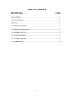
Page 3: ...AGE Important Notes 2 Service Connections 4 Introduction 5 1 0 Installation Instructions 6 2 0 Information to Steam Fitter 8 3 0 Operating Instructions 10 4 0 Periodic Maintenance 12 5 0 Cleaning Instructions 14 6 0 Troubleshooting 16 ...

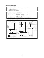
Page 4: ...e of water quality consult a FAILURE OR MALFUNCTION OF THIS APPLIANCE DUE TO POOR WATER QUALITY IS NOT COVERED UNDER WARRANTY Water which fails to meet these standards should be treated by installation of water conditioner 7 0 8 5 Less than 1 5 PPM Less than 13 PPM WATER QUALITY STATEMENT Less than 20 PPM Less than 60 PPM Pressure reducing valve is required if incoming pressure exceeds 50 PSI 345 ...

Page 5: ...ave been generated in the heat exchanger and ready pilot light will come on OFF shuts off the steam supply to the boiler and opens the automatic blowdown valve if so equipped emptying the boiler and releasing water and steam to the drain The manual blowdown valve will have to be opened to drain if not equipped with automatic blowdown valve 2 Boiler pressure gauge should read 9 11 psi during operat...

Page 6: ... connections Allow enough space between any other piece of equipment or wall for service access Service to the controls may be required on the left and or right side panels of the cabinet INSTALLATION CODES AND STANDARDS The appliance must be installed in accordance with In Canada Provincial and local codes or in the absence of local codes with the Canadian Electric Code CSA C22 1 latest edition C...

Page 7: ...unit back in position and re level left to right and front to back 6 Bolt and anchor appliance securely to the floor 7 Seal bolts and flanged feet with Silastic or equivalent compound 8 Make service connections as indicated WARNING Electrical and grounding connections must comply with applicable portions of the National Electrical Code and or other local electrical codes WARNING Disconnect electri...

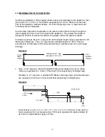
Page 8: ...rs of that pipe Thus a 1 pipe having a straight length of 120 10 feet is equivalent to 120 diameters of that pipe and will have a pressure loss of 1 psi through that pipe Example 1 Note in 3 4 pipe size that a Standard 90º Elbow and Angle Valve and a Globe Valve are equivalent to 1 8 feet 10 feet and 18 feet respectively of straight pipe Similarly in a 1 pipe size a standard 90º Elbow and Angle Va...

Page 9: ...iance to drain out water condensed steam from the line to assure clean dry steam to the appliance EXHAUST HOOD An exhaust system should be located directly above the boiler to exhaust steam and heat generated by the boiler PLUMBING CONNECTIONS WARNING Plumbing connections must comply with applicable sanitary safety and plumbing codes Water Supply Connection The incoming cold water supply connectio...

Page 10: ...er must be completed once daily prior to operation see instruction plate or above for boiler start up procedures With ready pilot light on preheat steamer compartment for one minute when the steamer is to be first used for the day or whenever the compartment is cold 1 Close compartment doors and set timer to 1 minute 2 When buzzer sounds set timer to the OFF position 3 Steamer is now ready for coo...

Page 11: ...oors slightly open 2 At the end of the day the steam supply must be shut off Open the door of cabinet base and turn off power switch Open manual drain valve If unit is equipped with automatic blowdown valve it will open and drain the boiler CAUTION If steam supply does not shut off during blowdown immediately discontinue use of appliance and call for service Each compartment is equipped with a rem...

Page 12: ... that the accumulation of sediment does not interfere with the movement of the float in the control Control must be flushed at least once a day When flushing control note water level in gauge glass allow the boiler to fill if necessary and also to come up to temperature Before flushing control note that water level in gauge glass is within operating range and the boiler pressure is at least 6 psi ...

Page 13: ...t if necessary 1 Water level control should be opened daily to blowdown sediment and scalant 2 Observe that the water in gauge glass is clean and clear Extreme murkiness in water indicates inadequate water quality 3 Safety valve should be tripped during operation once a week to assure that it functions properly 4 Keep all exposed cleanable areas of unit clean at all times CAUTION Disconnect the po...

Page 14: ...ush and mild detergent clean inside the drain opening ensuring there is no food residue or blockage Clean the drain screen and replace in its original position 4 Wash gasket sealing surface with mild detergent to remove harmful food acids and rinse 5 Water level control should be opened daily to blow down sediment and scalant 6 Observe that the water in gauge glass is clean and clear Extreme murki...

Page 15: ...ce 3 4 pipe cap OR union fitting 5 Open water supply to appliance allowing water to fill Generator tank to required level On appliances with Manual Blowdown turn ON power switch Boiler will fill to the required level 6 Let appliance cycle allow two hours for descaling and cleaning DO NOT TURN STEAM ON 7 Open both the blowdown and water level control valves for complete drainage and then close both...

Page 16: ... water level control valve is closed 5 Supply water pressure too low AUTOMATIC BLOWDOWN VALVE DOES NOT DRAIN 1 Defective Blowdown valve 2 Heat exchanger build up of scalant clogging drain lines and valve HEAT EXCHANGER ACHIEVES PRESSURE SLOWER THAN NORMAL 1 Heavy build up of lime on heat exchanger tubes 2 Steam supply pressure too low SAFETY VALVE BLOWS 1 Defective safety valve 2 Pressure too high...

Page 17: ...e low signal to 13 0 psi 2 OVERRIDE PRESSURE SWITCHES Allow pressure to increase to 13 psi Set the high signal to switch at 13 psi on the gauge and the low signal to 11 psi 3 OPERATING PRESSURE SWITCHES Set the high signal to switch at 11 psi on the gauge and the low signal to 9 psi Release pressure in boiler to below 9 psi Elements will come on Once pressure has reached 11 psi elements will shut ...

Reviews: