18
HE-12/HE-4
Instruction Manual
1
4
3
2
Operating Controls & Indicators - MIDM-806C
Front Panel
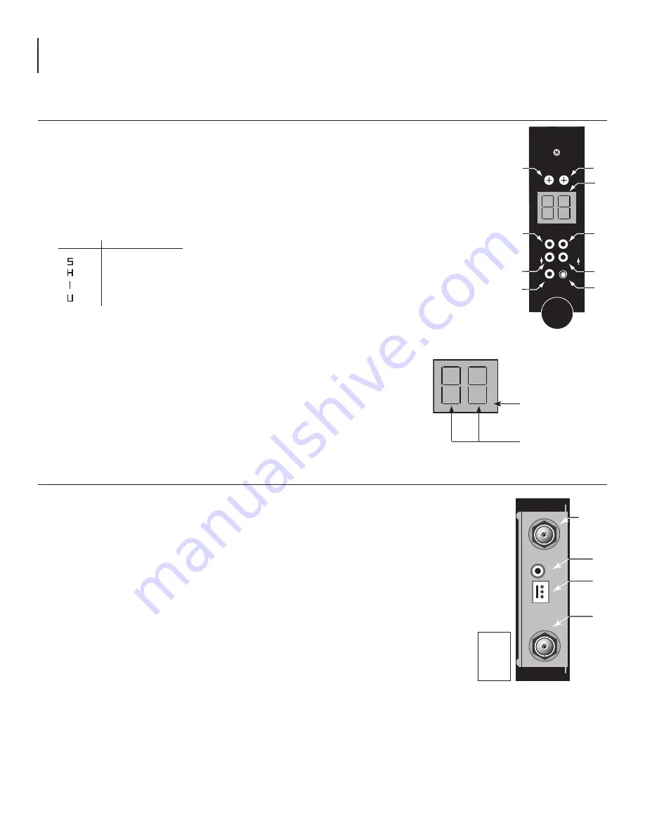
All operating controls are located on, or are accessible from the front panel.
MIDM-806C
Stock no. 7740C
V
A
PWR
C/ANT
+100
BLONDER
TONGUE
1
5
6
9
3
4
7
8
2
CH
CH
LOCK
.
.
1.
Video
- Adjusts video output level
2.
Audio
- Adjusts audio output level
3.
Channel LED
- Displays ANT or CATV channel number
4.
C/ANT Mode Button
- Push button to enter the mode selection menu. Use the
channel Up/Down keys to select the type of channel system required as follows:
Display
Channel System
STD CATV
HRC
IRC
Broadcast U/V
5.
Power -
On / Off push button
6.
Channel Down
- Increments channel by -1
7.
Channel Up
- Increments channel by +1
8.
+100 LED
- When depressed, red LED lights to indicate
channels 100 and higher
9.
Lock
- Depressing Lock button locks present channel or mode in memory prevent-
ing inadvertent change. A user must depress the lock button again for any chan-
nel mode/changes
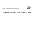
All the connectors are located on the rear panel.
1.
Video Output
- Standard neg a tive sync video at a 0.5 to 1.5 Vp-p level.
2.
Audio Output
- Adjustable 0.5 to 1.5 Vp-p
3.
Power
- The polarized power connector a12 VDC +5 VDC and ground
4.
ANT/CATV
- RF input from antenna or CATV drop
.
.
3. LED Display - Lights when in standby
LOCK Indicator
Channel Display
DC Input
+5 V
+12 V
GND
Rear Panel


