
9
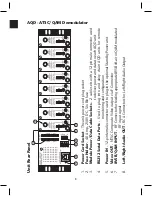
AQD - ATSC/QAM Demodulator
Operating Interface Instructions
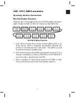
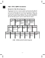
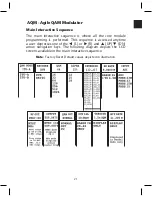
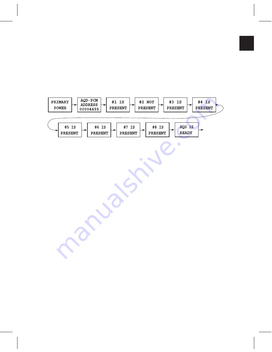
Boot-Up Display Sequence
When the unit is first plugged in for use, the PCM displays the appro-
priate module condition on the LCD readout as depicted below.
Boot-Up Display Sequence
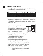
1. Each control module has a unique module address that is set
at the factory which is displayed immediately following the
primary or secondary power source status. This address is used
for remote software capability only.
2. Each module status is identified and reported on the LCD. If a
module is identified it is listed as PRESENT or NOT PRESENT if
not connected or identified by the PCM.
3. Upon completion of the boot-up sequence the AQD is ready
for use and will proceed to the loop display sequence.
Summary of Contents for AMM-806
Page 86: ...79 TVCB PC Installation ...
Page 93: ...86 SMI Installation Torque Patterns 1 Start Here 2 3 4 5 6 1 Start Here 2 3 4 4 PORT 8 PORT ...
Page 125: ...118 Fiber Optics Fiber Loss vs Path Length Single Mode 1550 nm ...
Page 156: ...149 Cable TV Channel Format NTSC NTSC Composite Video Waveform ...
Page 157: ...150 US Frequency Spectrum ...
Page 158: ...151 FCC Aeronautical Band Frequencies Used for Communication and Navigation ...
Page 175: ...168 Common CATV Symbols ...
Page 176: ...169 Common CATV Symbols ...
Page 177: ...170 Digital L Band Distribution Symbols ...
Page 178: ...171 Digital L Band Distribution Symbols ...
Page 183: ...176 Typical Cable Attenuation Chart in dB 100 Feet 68 F 20 C ...
Page 187: ...180 Echo Rating Graph ...
Page 188: ...181 Signal to Interference Limits Non Coherent Carriers ...
Page 190: ...183 Heterodyne Modulator Analog ...
Page 191: ...184 Heterodyne Processor Analog ...
Page 213: ...206 Multiplexers ...
Page 285: ...Rev 8 0 ...