186
Broadband RF Network Powering
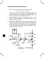
6. Determine the voltage across the next span of cable.
0.75 x 1.36 Ohms = 1.02 Volts
Therefore the voltage at the output of the bridger amp is 44.5
volts. The total current at the input to the bridger amp is 2.0
amps. This is the sum of both output legs of the bridger (1.5A)
and the current draw of the bridger amp itself.
7. Continue working towards the headend until the current
draw is 40-50% of the power supplies rated capability or the
voltage level nears 60 volts.
8. At this time, a guesstimate of where to place a power block
in the section between the power supply and headend must
be made. Add the current draw for the line extender(s) off
each trunk station to the trunk station current requirements.
A few trial calculations will show how many amplifiers can be
powered going in this direction.
Summary of Contents for AMM-806
Page 86: ...79 TVCB PC Installation ...
Page 93: ...86 SMI Installation Torque Patterns 1 Start Here 2 3 4 5 6 1 Start Here 2 3 4 4 PORT 8 PORT ...
Page 125: ...118 Fiber Optics Fiber Loss vs Path Length Single Mode 1550 nm ...
Page 156: ...149 Cable TV Channel Format NTSC NTSC Composite Video Waveform ...
Page 157: ...150 US Frequency Spectrum ...
Page 158: ...151 FCC Aeronautical Band Frequencies Used for Communication and Navigation ...
Page 175: ...168 Common CATV Symbols ...
Page 176: ...169 Common CATV Symbols ...
Page 177: ...170 Digital L Band Distribution Symbols ...
Page 178: ...171 Digital L Band Distribution Symbols ...
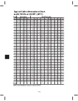
Page 183: ...176 Typical Cable Attenuation Chart in dB 100 Feet 68 F 20 C ...
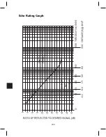
Page 187: ...180 Echo Rating Graph ...
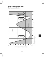
Page 188: ...181 Signal to Interference Limits Non Coherent Carriers ...
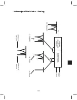
Page 190: ...183 Heterodyne Modulator Analog ...
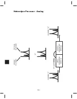
Page 191: ...184 Heterodyne Processor Analog ...
Page 213: ...206 Multiplexers ...
Page 285: ...Rev 8 0 ...

