7
Clearview NTSC16
Quick Guide
Troubleshooting
For technical support please contact us at 1-800-523-6049 between the hours of 8am and 5pm EST.
Please refer to the User Manual for additional information.
Non-Standard Network Configuration
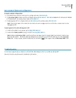
Example network configuration:
1. The Video Source device's control port is configured to be at
192.168.3.18
.
2.
The
Clearview NTSC
IP Video ports are configured to be at
192.168.6.71
-
192.168.6.86
(
DC1:1
at “192.168.6.71”,
DC2:1
at “192.168.6.79”, etc.) with subnet masks of
255.255.0.0
.
3. The Management PC is configured to be at
192.168.3.5
with a subnet mask of
255.255.0.0
.
Note:
The subnet mask of the Video Source device must be configured to be on the same subnet mask as the
Management PC.
Accessing devices from the Management PC:
•
To access the Video Source device, go to
http://192.168.3.18
•
To access the
Clearview NTSC
unit, go to DC1:1 at
http://192.168.6.71
Note:
Additional
Clearview NTSC
units sharing the same network with a single Video Source device need to have
their decoder (DC1:1 - DC2:8) IP addresses assigned to avoid collisions with DC IP addresses on other
Clearview
NTSC
units. In other words, all DC IP addresses on a network *
must
* be unique across all
Clearview NTSC
units.


