background image


CMTS Edge Series Universal Quick Start Guide 

P a g e

 | 

4


3.


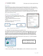
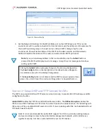
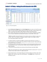
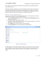
Set the Network IP Address for the SFP+/10Gbe port on the CMTS (Figure 6). If this is a lab 
environment with no uplink connection for Internet access yet, this address is still necessary for 
the Local Provisioning setup in the next section.  When CMTS is being setup for a live 
environment, this will be the address of the CMTS on the data network, and the Gateway 
Address should be the address of the router connected to the CMTS uplink port.  
 

Note: 

If you put a Gateway address in that is unreachable, once the 

Submit

 button is 

pressed the CMTS will display an error message.  Accept the error message and continue 
setting up the CMTS. 


Section 3 

 Setup DHCP and TFTP Services for CMs 

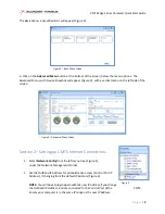
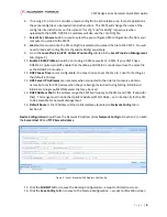
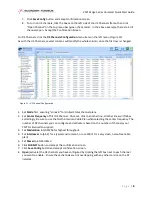
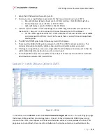
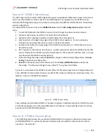
The CMTS can provide DHCP and TFTP server services internally, to provide DHCP IP Addresses and CM 
config files to the CMs. 
 

Global DHCP

 enables the CMTS to send DHCP addresses to CMs.  The 

CPE Switch option 

enables the 

CMTS to send DHCP addresses to CPEs from the same IP pool as the cable modems.  For lab testing with 
CMs and no CPEs, only Global DHCP needs to be ON.  If you are testing with CPEs, both Global DHCP and 
CPE Switch needs to be ON. 
 

Note: It is not recommended to enable DHCP support for CPE in a production setting because 
end users could gain access to the cable modem management network, which introduces a 
significant security risk! Use an external DHCP server for CPE devices. 


Figure 6 

 Network Config 

Clicking the

 Submit

 button will apply changes to the 

Running Configuration

.  

The 

Save Config

 button on the top right must be clicked to save changes to 

non-volatile memory for the 

Startup Configuration

If the 

Save Config

 button is not clicked, and the CMTS is power cycled or loses 

power, the unit will revert to previous settings when it is powered back on. 

Summary of Contents for CMTS Edge 16

Page 1: ...CMTS Edge Series Universal Quick Start Guide May 2022 Version Draft ...

Page 2: ...hown in Figure 1b 2 Connect a computer to the Control Port of the CMTS as shown in Figure 1a For Reference The default emergency recovery address of the SFP 10Gbe port of the CMTS is 192 168 168 100 24 To access the CMTS through this port set your computer to an IP address in that subnet such as 192 168 168 105 24 Note this IP address is not changeable so you must avoid using this IP address range...

Page 3: ...up CMTS Internet Connections 1 Select Network Config from the left menu tree Figure 5 under the Network Management Folder 2 Set the Outband IP Address for administrative access Control Port IP Address if changing from the default IP address Figure 6 NOTE You will have to login again with the new IP address if you change the Outband IP Address and are connected to the Control Port of the CMTS Ensur...

Page 4: ...rovide DHCP IP Addresses and CM config files to the CMs Global DHCP enables the CMTS to send DHCP addresses to CMs The CPE Switch option enables the CMTS to send DHCP addresses to CPEs from the same IP pool as the cable modems For lab testing with CMs and no CPEs only Global DHCP needs to be ON If you are testing with CPEs both Global DHCP and CPE Switch needs to be ON Note It is not recommended t...

Page 5: ...BMIT button to save to Running Configuration Accept confirmation screen 4 Click Save Config button to save to Startup Configuration Accept confirmation screen 5 Click the Load CM Config button to open a dialog box for uploading pre configured DOCSIS CM configuration files to the CMTS CM Profile allows selection of cm cfg for 2 0 CMs or cm30 cfg for DOCSIS 3 0 CMs NOTE CMTS does not ship with a def...

Page 6: ...eckbox as DOCSIS 3 1 modems will use the same file as the DOCSIS 3 0 modems 11 DHCP Lease Time is user configurable You may choose to set the time to 1 hour for testing as the default is 10 days 12 DNS Server IP Addresses are necessary when connected to the Internet to resolve domain names but only for CPE devices when they are being provisioned during testing 8 8 8 8 and 8 8 4 4 are Google public...

Page 7: ...entire column will populate with the same value 3 The Center Frequency and Frequency Width must be set so the channels do not overlap A center frequency of 15 4 MHz and Frequency Width of 3 2 MHz means the channel will occupy the spectrum from 13 8 17 0 MHz 4 The Frequency Width and Modulate Template determine the total bandwidth bitrate capacity of that upstream channel For US channels a QPSK cha...

Page 8: ...rst DS Channel Once set click to another line all other lines will follow accordingly Be sure to use the North American Cable Plan when selecting the center frequency The number of DS channels you can configure and activate is based on the number of channels your CMTS is licensed to support 3 Set Modulation to QAM256 for highest throughput 4 Set Interleaver to 64 2 for a typical environment or use...

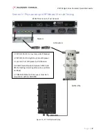
Page 9: ... 2 CMTS DS Port to High Freq Side of Diplexer 3 Common Port of Diplexer to Distribution 4 40 dB total Attenuation between CMTS and CMs for testing including attenuators splitters and taps 5 If DMM 5500 Series CM is used must be in conjunction with LG 5500 STB BT CMTS Series Lab Test Network Diplexer Attenuators Splitter Tap Figure 12 RF Test Network Setup ...

Page 10: ...gh Frequency side of the Diplexer 5 There must be 40 dB of attenuation between the CMTS and CM for proper operation This includes attenuation created by splitters taps and any inline attenuators you install 6 If testing to a single CM you can use a single cable from the Diplexer Common port to the CM with 40 dB of total attenuation inline on the common port 7 For multiple CMs under test use splitt...

Page 11: ...such as DS Receive Power Level and DS SNR as shown in Figure 13 you must enable Remote Query 1 Open the Remote Query Config menu item under the Device Terminal Management section of the left menu Figure 14 2 Turn Remote Query on select the radio button 3 Set the Source IP to be the IP address of the Network IP address SFP 10Gbe port This should be the bottom choice in the drop down menu 4 Hit the ...

Page 12: ...nk Channel a 6 MHz wide carrier within the OFDM channel that carries information to the CM about the OFDM channel This is what the CM first locks on to and must be within the OFDM channel spectrum 7 Once all settings have been made Submit the changes to the Running Configuration and Save Config to the Startup Configuration 8 Select the channel s you just modified and click the Open OFDM Channel to...

Page 13: ...onfiguration and Save Config to the Startup Configuration 6 Select the channels you just modified and Open OFDMA Channel to activate the channel s The status will change from a yellow X to a green Check Mark See Figure 16 for an example of the settings of an OFDMA channel setup in a lab environment Other settings will be further explained in the Command Reference Guide Figure 17 shows the CM List ...

Page 14: ...S downstream carrier and has locked onto the downstream init r2 The CMTS sent a CONTINUE ranging response to the CM with or without adjustments as part of the secondary ranging which is meant to tell the modem to adjust its transmit power level in order to be seen by the CMTS at its configured upstream power level value init rc The CMTS sent a SUCCESS ranging response to the CM ranging complete in...

Page 15: ...ion and or upstream mode DOCSIS 3 0 f online An f prefix before one of the online CM states indicates that the CM is online but failed bonding during initial ranging p online The p prefix before one of the online CM states means that the CM is in partial operation with some impairment to one of the channels reject c The CMTS has rejected the configuration in a registration request This could be fo...

Reviews: