CMTS Edge Series Universal Quick Start Guide
P a g e
|
6
6.
If running 2.0, 3.0 and 3.1 modems, load a config file in each relative area. In most applications,
the same config file can be loaded into both sections. The CMTS will change the name of the
config file internally from your file name to
“
cm.cfg
”
and
“
cm30.cfg
” respectively
when
uploaded to the CMTS. DOCSIS 3.1 modems will also use the cm3.0.cfg file.
7.
Select File / Browse
button is used to select the pre-configured CM configuration file from your
computer to upload to the CMTS.
8.
Load
button is used once the CM config file is selected, to upload the file to the CMTS. You will
need to load each config file (cm.cfg and cm30.cfg) separately.
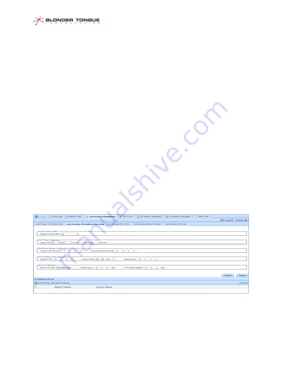
9.
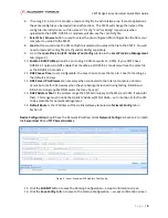
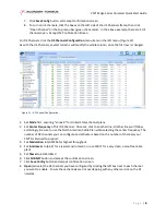
Go to the
Local-Provision IPV4 Address Pool Config
sub-tab in the
Local-Provision Management
tab. (Figure 9)
10.
Enable 3.0CM Profiles
should be on if using 3.0 CMs as well as 2.0 CMs. If your CMTS has a
DOCSIS 3.1 option, do NOT enable that checkbox, as DOCSIS 3.1 modems will use the same file
as the DOCSIS 3.0 modems.
11.
DHCP Lease Time
is user configurable. You may choose to set the time to 1 hour for testing, as
the default is 10 days.
12.
DNS Server IP Addresses
are necessary when connected to the Internet to resolve domain
names but only for CPE devices when they are being provisioned during testing. 8.8.8.8 and
8.8.4.4 are Google public DNS servers that may be used.
13.
DHCP Address Pool
is the address range the CMTS will supply to the CMs (and CPEs, if setup for
that). This range must include the
Uplink IP Address
(SFP+/10Gbe
–
set in Section 2) for the CM
to be accessible for network management .
14.
Default Route
Is the IP Address of the Uplink Gateway (entered on
Network Config
tab in
Section 2)
Device Configuration
should have the
Network IP Address
(From
Network Config
tab, Section 2) on both
the
Server Host IP
and
TFTP Server Address.
15.
Click the
SUBMIT
button to save the
Running Configuration
–
accept confirmation screen
16.
Click the
Save Config
button to save to the
Startup Configuration
–
accept confirmation screen
Figure 9
–
Local-Provision IPV4 Address Pool Config


