6
FOCN
Instruction Manual
Internal Adjustments
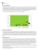
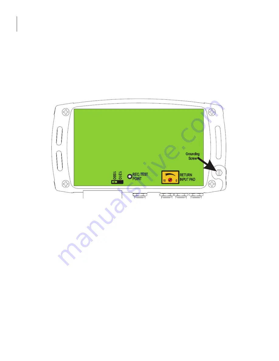
The FOCN receiver has two user adjustments inside the unit. One is used to change the Forward Receive level test point
calibration between 1310nm and 1550nm optical input ranges. The other is to set the OMI of the return band transmit-
ter, (if equipped) this will be discussed later on. The unit should not be operated for extended periods with the top cover
removed. This is because of RF ingress and contamination from dirt or other objects. When replacing the top cover, be
sure to firmly tighten all thumbscrews. RF ingress or oscillation can be caused by loose screws.
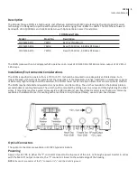
The locations of the internal adjustments are shown in the following diagram.
Return Transmitter Setup
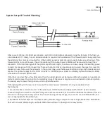
The specification for the return band transmitter RF input level is -58 dBmV/Hz (measured at FOCN RF Out Port). This
value operates the system at NPR threshold. The FOCN has an adjustable attenuator in the return path. Also included
is a -20 dB test point in the return path. The single carrier equivalent of -57 dBmV/Hz is +9 dBmV. The return pad must
be adjusted to set the carrier to +9 dBmV actual after the attenuator. With a test carrier present at the port (+19 dBmV
max), measure its level at the return -20 dB test point. Adjust the pad for a -20 dB test point reading of -11dBmV return
input.
External Test Points
The FOCN has three external test points. The received “Optical Power” test point is calibrated at 1V per mW @ 1310
nm, it should be measured with a high impedance voltmeter. This test point is for long term monitoring purposes as
well as initial setup. The optical power should be measured with a power meter at the time of installation. The input
test point is calibrated at the factory at 1310 nm. The value at 1550 nm may be off by 15% due to diode variations. The
input test point reading will be considerably off if the input wavelength is 1550 nm and the internal jumper has not
been changed. The jumper is located inside the unit next to the receive level test point as shown above. The position
closest to the test point is for 1310nm, and the position farther from the test point is for 1550nm.
The Forward Test Point is -20dB from the RF output of the receiver. If the RF out is +28dBmV, then the test point should
be approxi8dBmV.
The Return Test Point is -20dB from the RF input going to the return transmitter. Optimal input should be +14dBmV, so
the test point should read -6dBmV.


