background image

Manual

Connect Landscape

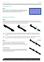
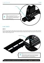
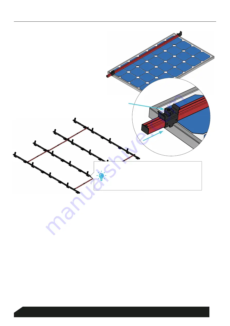
Place the Measuring profile (A) across 

the breadth of the panel, push home 

the slide (B) and turn it tight using 
the knob (C).

(B) Slide 

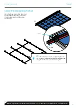
TIP:

From the outset, be sure to use right angles of 

90º. If you do, the mounting system will always be 
straight and the solar panels will always fit.

(C) Turn 

 (A)

USING THE MEASURING PROFILE

6

Blubase 

|

 Lingenstraat 9 

|

 8028 PM Zwolle, Nederland 

|

 T. (+31) 085-8000 501 

|

 info@blubase.nl 

|

 www.blubase.com

Summary of Contents for connect Landscape South

Page 1: ...Landscape South Manual...

Page 2: ...e the loads on the building due to the additional weight of the PV system the loads on the building due to the changed geometry of the roof plan the loads on the building due to the dynamic wind press...

Page 3: ...olar panels on roofs over 12 metres you may need to take additional measures Please consult your contact person Measure the free edge region from the outer border see the blue border in Figure C You c...

Page 4: ...es of a basic component As a result the mounting system will be raised and will not move TIP It is crucial that you maintain straight lines and 90 degree angles when mounting Only then will the solar...

Page 5: ...h of the solar panel determines the spacing between the rows Determine the exact distance using the Measuring profile Repeat these steps for all rows to carry out the mounting plan The next page conta...

Page 6: ...it tight using the knob C B Slide TIP From the outset be sure to use right angles of 90 If you do the mounting system will always be straight and the solar panels will always fit C Turn A USING THE M...

Page 7: ...rilled holes STAP 5 Torque 5Nm Place the solar panels against the mounting points Next conceal the cables in the cable management system STAP 6 Click the clamps into the basic component and turn them...

Page 8: ...It should be easy to place the return cable on the outside through the front cable conductor The cable tray contains a shielded area for the other cables STAP 7 A cable clip has already been pre moun...

Page 9: ...e solar panels will protect against the wind themselves Torque 5Nm CLICK Place the rear plates in the fastening points at the bottom of the stand Each stand has two rough drilled threaded holes top an...

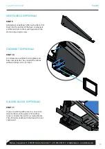
Page 10: ...s are available for side plates and basic components They conduct the cables without risking cut ins or cracks STAP 10 RAISING BLOCK OPTIONAL If you are working with gravel or you wish to elevate the...

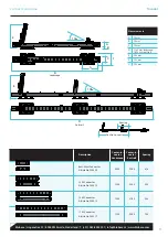
Page 11: ...3 1320 2000 320 1500 Connector Article No 500015 1500 2180 500 1700 Connector Article No 500017 1500 2380 700 E 130 B A G C F Landscape Portrait E 100 D D Spacing Centre to centre Measurements A 50 mm...

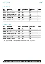
Page 12: ...BACK PLATES BALLAST BOXES above 1620mm the PV panel is no longer supported at the bottom Check the manual if this is allowed 12 Blubase Lingenstraat 9 8028 PM Zwolle Nederland T 31 085 8000 501 info b...

Page 13: ...nd or construction We therefore recommend that the structural calculations for an existing building are updated by a specialist taking into account the solar panels to be placed and current regulation...

Reviews: