background image

MAGNUM ETX 


BIOS Setup 

Page | 26  


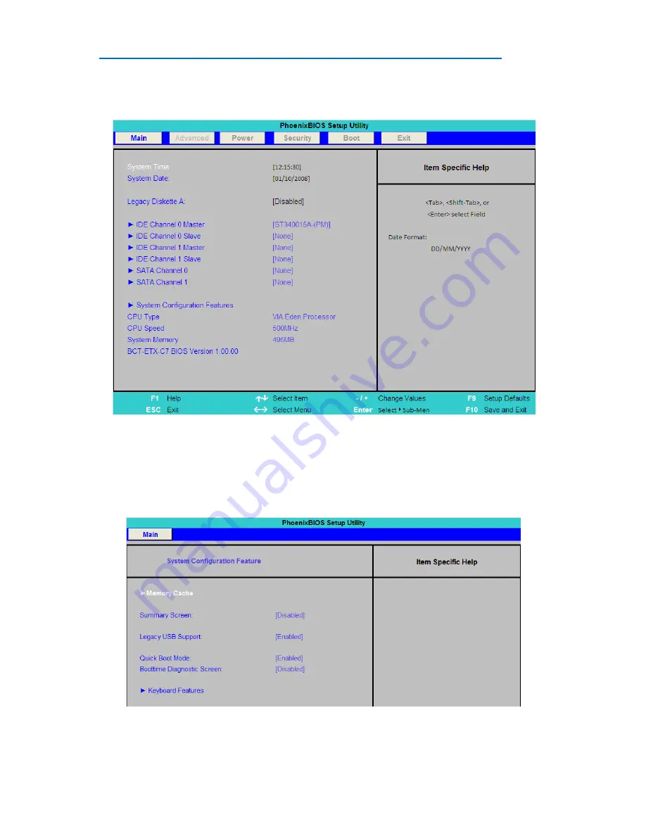
Main Menu 


Picture B1 

 
The Main menu allows the setting of Date and Time, as well as providing details of IDE devices fitted to the 
unit.  
 
Note: In the Boot menu shown later, SATA Channel 0 and 1 are equivalent to IDE 4 and IDE 5 respectively 
 

System Configuration Feature Sub Menu 


Picture B2 


Summary of Contents for Magnum ETX

Page 1: ...Page 1 MAGNUM ETX Biscuit Format Single Board PC User Guide Document Reference Product User Guide Document Issue 1 0...

Page 2: ...gnetic Compatibility 11 Quick Start 12 Assembly 13 Daughter Board connector locations 13 Cooling 15 Stack Heights and Clearances 17 Connections 18 J1 PCI VIO Select 19 J2 Vcc LCD 19 SW1 Power CF Selec...

Page 3: ...MAGNUM ETX Table Of Contents Page 3 Power Menu 30 Security Menu 31 Boot Menu 32 Exit Menu 33 Maintenance 34 Amendment History 35...

Page 4: ...p Technology Ltd Limitations of Liability In no event shall Blue Chip Technology be held liable for any loss expenses or damages of any kind whatsoever whether direct indirect incidental or consequent...

Page 5: ...io frequency energy and if not installed and used in accordance with the instruction manual may cause harmful interference to radio communications Operation of this equipment in a residential area is...

Page 6: ...connectors are located and their pin out details How to upgrade the system Bios Setup Connector Details Design Considerations Maintenance details We strongly recommend that you study this manual care...

Page 7: ...and 2GHz versions offer a higher performance solution The processor maintains full backward compatibility with the 8086 80286 i386 and Intel486 processors It supports both read and write burst mode bu...

Page 8: ...nd ATA 133 100 66 33 EIDE HDD quad ports dual connectors 512MB I2 C EEPROM providing non volatile storage Audio Integrated AC97 controller Line In Out Microphone In Communications Quad USB ver 2 compl...

Page 9: ...0 CPU utilisation General Operating Storage Temperature 20 C to 70 C Operating Temperature 0 C to 60 C Note faster CPU speeds will require active cooling to achieve Operating limit Relative humidity...

Page 10: ...ear an approved wrist strap or if that is not possible touch a suitable ground to discharge any static build up before touching the electronics This should be repeated if the handling continues for an...

Page 11: ...good metal to metal contact around the internal electronics Any metal back plate must be securely screwed to the chassis of the computer to ensure good metal to metal i e earth contact Metal screened...

Page 12: ...to ensure that your solution is capable of cooling the processor throughout the desired operating temperature range Note that the upper operating limit of 60 C is for the board operation in free air w...

Page 13: ...of which are SATA connectors Connection to the host board is with four Hirose plug connectors part number FX8 100P SV which mate with corresponding Hirose socket connectors eg part number FX8 100S SV...

Page 14: ...the daughter board will only fit on one orientation Trying to force the daughter baord in the wrong orientation may damage the connectors Figure 3 Align daughter board connectors with the host board I...

Page 15: ...ear in mind that the greater the volume of air that can flow through the enclosure the greater the cooling effect and the lower the temperature rise above the ambient air temperature However the volum...

Page 16: ...solution it is necessary to spread some thermal grease to the surface of the boss which will contact the CPU Thermal grease is required as thermal pads provide less thermal conductivity than required...

Page 17: ...4mm As the fan draws air down from the top and pushes out through the sides in this instance there is a requirement for at least 25mm clear space above the fan to ensure the fan operates efficiently T...

Page 18: ...ctions Page 18 Connections All connections to the Magnum ETX are made via the Carrier board Connector positions are shown below Figure 9 Front Connectors Figure 10 Top Side Connectors Figure 11 Bottom...

Page 19: ...P17 LCD J1 PCI VIO Select Connect Output 1 2 5V 2 3 3V3 Note If 5V is selected some modern PCI cards which are 3V3 Signalling may not work Conversely if 3V3 is selected then older legacy 5V signalling...

Page 20: ...NC 10 NC P7 Parallel Port Pin Assignment Pin Assignment 1 PSTRB 2 P_AFD 3 PPD0 4 P_ERR 5 PPD1 6 P_INIT 7 PPD2 8 P_SLIN 9 PPD3 10 GND 11 PPD4 12 GND 13 PPD5 14 GND 15 PPD6 16 GND 17 PPD7 18 GND 19 P_A...

Page 21: ...wer Pin Assignment 1 12V 2 0V 3 0V 4 5V P14 GPIO Audio Pin Assignment Pin Assignment 1 GPIO 0 2 GPIO 1 3 GPIO 2 4 GPIO 3 5 GPIO 4 6 GPIO 5 7 GPIO 6 8 GPIO 7 9 5V 10 5V 11 GPIO 8 12 GPIO 9 13 GPIO 10 1...

Page 22: ...LVDS Pin LCD LVDS 1 INVPWR INVPWR 2 INVPWR INVPWR 3 GND GND 4 GND GND 5 VCCLCD VCCLCD 6 VCCLCD VCCLCD 7 VPOT VPOT 8 GND GND 9 CB5 ZC 10 CB4 ZC 11 CB3 Z2 12 CB2 Z2 13 CB1 Z1 14 CB0 Z1 15 N C N C 16 N...

Page 23: ...ND 2 CCLK 3 GND 4 CLP 5 CFLM 6 GND 7 GND 8 GND 9 CR0 10 CR1 11 CR2 12 GND 13 CR3 14 CR4 15 CR5 16 GND 17 GND 18 GND 19 CG0 20 CG1 21 CG2 22 GND 23 CG3 24 CG4 25 CG5 26 GND 27 GND 28 GND 29 CB0 30 CB1...

Page 24: ...aid driver for the VT8237 Southbridge device For Audio driver run the setup exe file from the Drivers SBPC ETXCN700 Audio folder Lastly for the LAN driver use Device Manager and when prompted point th...

Page 25: ...escriptions of the main user configurable options are provided for information The following pages do not go into great depth so if you require more in depth data on particular BIOS settings please co...

Page 26: ...in menu allows the setting of Date and Time as well as providing details of IDE devices fitted to the unit Note In the Boot menu shown later SATA Channel 0 and 1 are equivalent to IDE 4 and IDE 5 resp...

Page 27: ...abled for a summary of devices and their resources to eb shown after POST and prior to OS load Advanced Menu Picture B3 The Advanced Menu pages provide the means to customise the configuration of the...

Page 28: ...n Sub Menu Picture B4 This sub menu allows the reservation of system resources for use with legacy ISA devices Chipset Devices Sub Menu Picture B5 The Chipset sub menu allows for PATA SATA USB Audio a...

Page 29: ...s selection of display type I O Device Configuration Picture B7 This sub menu allows for controlling the Serial Parallel and Floppy interfaces Hardware Monitor Picture B8 This sub menu shows on board...

Page 30: ...A Bridge which can be disabled as the host board does not support ISA cards and the Onboard Watchdog Timeout Power Menu Picture B10 The Power Menu allows the user to set the state for power failure Op...

Page 31: ...MAGNUM ETX BIOS Setup Page 31 Security Menu Picture B11 The Security menu allows for BIOS and Boot passwords to be set...

Page 32: ...ther device is required then one of the 8 needs to be removed from the Boot Order List by first selecting it and then typing the X key A device form the Excluded list can be added to the Boot Order li...

Page 33: ...MAGNUM ETX BIOS Setup Page 33 Exit Menu Picture B13 As well as offering the means to exit with and without saving settings this menu also allows for the System BIOS Default Settings to be restored...

Page 34: ...maintenance After a period of several years it may be necessary to replace the battery if it cannot maintain the CMOS clock whilst the AC power is disconnected If an active cooling solution is fitted...

Page 35: ...ster CH3 9EX U K Telephone 44 0 1829 772000 Facsimile 44 0 1829 772001 www bluechiptechnology co uk Plasma PC Sales PlasmaPC bluechiptechnology co uk Single Board Computer Sales singleboardcomputer bl...

Reviews: