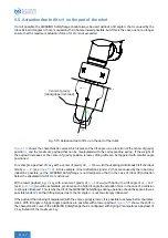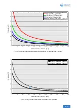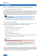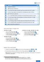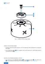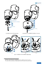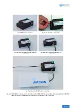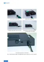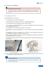
6.3.1 Cable connections
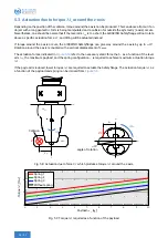
• On the input side, either directly connect the Safetyflange to the AIRSKIN® Connection Box via magnetic
cable or via a chain of AIRSKIN® Pads.
• On the output side, connect the Safetyflange to a gripper’s AIRSKIN® Pad (if available); otherwise use an
end connector.
• Connect external cables as intended
• Before you plug it in, position the external cable so that the marking on the connector matches the marking
on the Pad.
Installation information
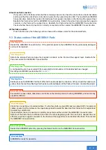
When attaching the cables, ensure that no tractive force is acting on the connector, other-
wise this can lead to the AIRSKIN® malfunctioning.
6.4 Connecting the AIRSKIN® Safetyflange to the PLC or the robot controller
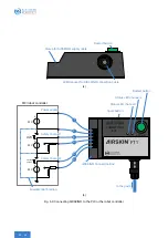
The AIRSKIN® Safetyflange or an AIRSKIN® System is connected via the AIRSKIN® Connection Box.
Danger to life from electric current
The system should only be connected by a qualified electrician. Pay attention to the safety
instructions (see
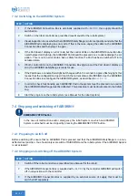
6.4.1 Voltage
Only connect AIRSKIN® to the connections on the robot controller that are indicated in the robot’s User’s Manual,
or to a power source that is supplied.
If a power source is supplied, ensure potential equalization between AIRSKIN® and the robot in accordance with
the robot’s User’s Manual.
Potential equalization
The safety switches on AIRSKIN® are NOT potential-free. Proper functionality is not guar-
anteed if the ground potentials of the system/robot and AIRSKIN® are different.
6.4.2 Fuse
Ensure that the electrical network is adequately fused.
6.4.3 Electrical connection
• Lay the supply cable from AIRSKIN® to the controller so there is no risk of anyone stumbling over it and the
freedom of movement of the robot gets not limited.
• Use the AIRSKIN® Connection Box to connect the supply cable to the PLC / the robot controller in accordance
with the User’s Manual that is specific to the particular model of robot.

