background image

16

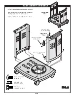
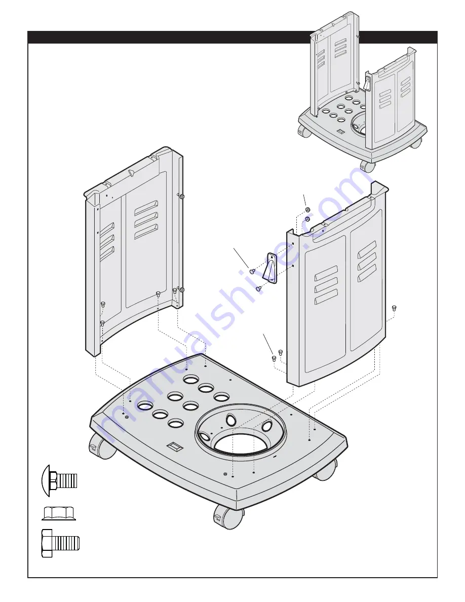
BASE CABINET ASSEMBLY

•  Attach Cabinet side panels to base as shown.

NOTE: 

Right panel has two holes located on 

the top right corner for bottle opener.

•  Attach bottle opener to right panel as shown.

FIG.2

Right hand

Panel

Assembled

View

SP84-18  (8)  
1/4-20 X .5 HEX HD BOLT 

SP84-18 (8)  1/4-20 X .5 HEX

HD BOLT 

SP53-16 (2)  1/4-20 

NUT HEX HD FLANGED

SP53-16 (2)  1/4-20 
NUT HEX HD FLANGED

SP83-18 (2) 1/4"-20X.50"
CARRIAGE BOLT

SP83-18 (2) 1/4"-20X.50"

CARRIAGE BOLT

Summary of Contents for FG50057

Page 1: ...NOT BE EXACTLY AS SHOWN C US Outdoor Gas Barbeque Grill Assembly manual and Use and Care IF YOU SMELL GAS 1 Shut off gas supply to the appliance 2 Extinguish any open flame 3 Open lid 4 If odour continues keep away from the appliance and immediately call your gas supplier or your fire department Do not store or use gasoline or other flammable vapours and liquids in the vicinity of this or any other a...

Page 2: ...ICH IF NOT AVOIDED WILL RESULT IN DEATH OR SERIOUS INJURY WARNING WARNING INDICATES AN POTENTIALLY HAZARDOUS SITUATION WHICH IF NOT AVOIDED COULD RESULT IN DEATH OR SERIOUS INJURY CAUTION CAUTION INDICATES AN POTENTIALLY HAZARDOUS SITUATION OR UNSAFE PRACTICE WHICH IF NOT AVOIDED COULD RESULT IN MINOR OR MODERATE INJURY WARNING Combustion by products produced when using this product contain chemic...

Page 3: ...lls or rails Do not use on or under balconies VENTURI TUBE VALVE CASTING Fig 1 61cm 24 46cm 18 Fig 2 10mm MODEL MAY NOT BE EXACTLY AS SHOWN WARNING WARNING WARNING DO NOT USE THIS GAS OUTDOOR APPLIANCE UNDER ANY OVERHEAD COMBUSTIBLE CONSTRUCTION WHEN DECIDING WHERE TO PLACE YOUR APPLIANCE FOLLOW THESE MINIMUM CLEARANCE DISTANCES TO ADJACENT COMBUSTIBLE MATERIALS WARNING 61 cm 24 inches from side o...

Page 4: ...thread on the outlet part of the valve Standard existing valves do not have these exterior threads Any attempt to connect a regulator with other than the i Mating Type 1 connector recognized by the large black coupling nut or ii Standard 510 P O L fitting by use of adapters or any other means could result in damage fire or injury and may negate the important safety features designed into the Type ...

Page 5: ...fill or repair your cylinder DO NOT allow the cylinder to be filled beyond 80 full Make sure the L P gas dealer checks the cylinder for leaks after filling LP CYLINDER EXCHANGE Many retailers that sell grills offer you the option of replacing your empty LP cylinder through an exchange service Use only those reputable exchange companies that inspect precision fill test and certify their cylinders E...

Page 6: ...gulator preset to this pressure is supplied with the barbeque and MUST be used This regulator is equipped with the Q C C Type 1 quick connect coupling system which incorporates the following safety features Figure 5 It will not allow gas to flow until a positive seal has been made Figure 6 It has a thermal element that will shut off the flow of gas between 115 and 150 C 240 and 300 F It also has a...

Page 7: ...gure 7B All hose connections Figure 7C including side burner tubing if equipped Figure 7D All valve connections Figure 7C D AREAS TO TEST ON NATURAL GAS BARBEQUES All hose connections Figure 7C All valve connections Figure 7C 7D HOW TO DO THE TESTING 1 With the barbeque console control knobs in the OFF position twist the valve on your propane cylinder 1 turn or the main natural gas valve on CLEANI...

Page 8: ...m soapy water and wipe dry Do not use citrisol abrasive cleaners degreasers or a concentrated grill cleaner on plastic parts Damage to and failure of parts can result CASTING INTERIOR AND WARMING RACK At least once a year remove all components from inside your barbeque Loosen any cooking residue with a scraping tool for large particles and a brass barbeque brush for smaller particles Scrub with ho...

Page 9: ... optional side burner and rotisserie burners the right small knob operates the side burner and the small left knob operates the rotisserie Figure 9A IGNITOR BATTERY Ensure AA BATTERY is installed correctly put negative side of battery in first Figure 9B CENTER BURNER WARNING DO NOT LIGHT SIDE BURNER WITH LID DOWN FAILURE TO DO SO MAY CAUSE SERIOUS BODILY INJURY AND OR PROPERTY DAMAGE WARNING ENSURE...

Page 10: ...d wait 5 minutes to clear the gas 7 Repeat steps 1 to 6 If burner still fails to light refer to Troubleshooting Guide to determine cause and solution or try the Match Lighting procedure Fig 11B CAUTION IF LIGHTING MAIN BURNERS ONLY ENSURE SIDE BURNER KNOB IS IN THE OFF POSITION MATCH LIGHTING PROCEDURE 1 Open the lid before lighting 2 Place an ignited lighter or lit match through the lighting hole...

Page 11: ...llow the lighting procedures step by step ensuring all valves including tank are off before starting RELIGHTING SAFETY WARNING If the burner flame goes out when your barbeque is in operation immediately turn off the control valves Wait five minutes for the gas to clear before attempting to relight the burner If the problem persists refer to the Troubleshooting Guide POSITIONING COOKING GRIDS Cooki...

Page 12: ...ATURES HIGH Setting Use the HIGH setting to preheat the barbeque sear meat such as steak to burn off any cooking residue from the grids after cooking your meal HIGH is rarely used for extended cooking MEDIUM Setting Most grilling or roasting of meat and vegetables as well as any baking is best done at a medium heat LOW Setting A low temperature is used when cooking lean meat or delicate items such...

Page 13: ... cylinder Follow correct lighting procedure Page 10 12 Perform leak test and correct leaks Page 7 Tighten regulator fully hand tight into cylinder Page 6 Check battery orientation Has battery been used previously Replace Battery Check to insure threads are properly engaged Button should travel up and down without binding If no sparks are generated with new battery and good wire connections module ...

Page 14: ...ners made of stainless steel depends almost entirely on proper use cleaning and maintenance This warranty does not cover failure due to improper use and maintenance PORCELAIN COOKING GRID Some OMC cook boxes and cooking grids are coated with a durable porcelain enamel Porcelain is essentially a glass coating Some chipping may occur if mishandled This will not affect the use or performance of the pa...

Page 15: ...led View TOOLS REQUIRED Extra Common Nuts Bolts are supplied Refer to diagrams to assemble your grill NOTE Some grill parts shown in the assembly steps may differ slightly in appearance from those on your particular grill model However the method of assembly remains the same ...

Page 16: ...right corner for bottle opener Attach bottle opener to right panel as shown FIG 2 Right hand Panel Assembled View SP84 18 8 1 4 20 X 5 HEX HD BOLT SP84 18 8 1 4 20 X 5 HEX HD BOLT SP53 16 2 1 4 20 NUT HEX HD FLANGED SP53 16 2 1 4 20 NUT HEX HD FLANGED SP83 18 2 1 4 20X 50 CARRIAGE BOLT SP83 18 2 1 4 20X 50 CARRIAGE BOLT ...

Page 17: ...Assembled View SP46 21 4 1 4 X1 2 SCREW HEX HD SP46 21 4 1 4 X 1 2 SCREW HEX HD SP84 18 2 1 4 20 X 5 HEX HD BOLT SP84 18 2 1 4 20 X 5 HEX HD BOLT Attach rear panel by sliding notches over screws on side panels as shown Tighten screws ...

Page 18: ...s Attach heat shield as shown Tighten screws FIG 5 Assembled View SP83 18 4 1 4 20 X 50 CARRIAGE BOLT SP83 18 4 1 4 20X 50 CARRIAGE BOLT SP53 16 4 1 4 20 NUT HEX HD FLANGED SP53 16 4 1 4 20 NUT HEX HD FLANGED SP61 21 7 10 B X 375 SCREW SELF TAP SP61 21 7 10 B X 375 SCREW SELF TAP ...

Page 19: ...on doors into upper holes as shown A Drop locking pins through lower holes in door into base assembly B Once in position rotate pins into locked position as shown FIG 5 Assembled View A B Locked position Pin SP17 32 2 HINGE PIN LOWER 10 24 NUT HEX HD FLANGED PIN HANDLE ...

Page 20: ...HE GAP AND THAT IS DIRECTED TO THE BOTTOM OF CABINET PROPANE HOSE REGULATOR SHOULD ALSO DIRECTED THROUGH THE GAP TO THE CYLINDER UNDERNEATH THE HEAT SHIELD WARNING FAILURE TO ENSURE ANY OF THESE WARNINGS MAY RESULT IN HAZARDOUS FIRE OR EXPLOSION CAUSING SERIOUS BODILY INJURY AND OR PROPERTY DAMAGE AND INVALIDATES WARRANTY IF HOSE IS TIED TO BURNER OR BASE FIRST REMOVE THE TIE AND PACKAGING AND THE...

Page 21: ... 18 4 1 4 20 X 75 MACHINE SCREW SP53 16 2 1 4 20 NUT HEX HD FLANGED WARNING DO NOT PASS HOSE BEHIND THE HEAT SHIELD WARNING DIRECT THE HOSE TO THE FRONT OF THE HEAT SHIELD AS SHOWN WARNING WARNING DIRECT THE HOSE TO THE FRONT OF THE HEAT SHIELD AS SHOWN HOSE ASSEMBLY SP86 18 4 1 4 20 X 75 MACHINE SCREW SP53 16 2 1 4 20 NUT HEX HD FLANGED WARNING FAILURE TO ENSURE ANY OF THESE WARNINGS MAY RESULT I...

Page 22: ...DANGER DANGER DO NOT PASS HOSE ABOVE SHIELD HOSE MUST NOT TOUCH ANY PART OF THE BASE WARNING ENSURE HOSE ASSEMBLY DOES NOT CONTACT THE CASTING OR ANY OTHER PARTS WHICH WILL GET HOT Important For Natural Gas models direct the hose through the hole in the base as shown ...

Page 23: ...l Smoker on hooks inside cover assembly Step 3 Install 3 grids as shown Step 4 Install warming rack into supports as shown Step 5 Install AA BATTERY into ignitor put negative side of battery in first Step 4 Step 3 Step 1 Step 2 BATTERY PILE AA BATTERY IGNITOR CAP Put negative side of battery in first FIG 7 ...

Page 24: ...f and drop into locking position B Insert wingbolt into middle hole in bracket to lock shelf in position C Position ice wine bucket and condiment tray as shown Insert side burner grill Assembled View F FIG 8 A B C SP87 18 1 4 20 X 5 4 SHELF LOCK WING BOLT SP87 18 1 4 20 X 5 4 WING BOLT ...

Page 25: ...itioned in tube end Attach side burner Ignitor wire to terminal on side burner bracket Ensure you read and understand warning below before proceeding FIG 9 A B Grooves Ignitor Wire Electrode WARNING CAUTION NEVER LIGHT THE SIDE BURNER WHILE THE SIDE BURNER LID IS DOWN THE SIDE BURNER LID SHOULD ALWAYS BE OPEN WHILE SIDE BURNER IS LIT FAILURE TO DO SO MAY CAUSE SERIOUS BODILY INJURY AND OR PROPERTY...

Page 26: ... tray as shown fully forward Ensure grease trap and tray are in position before using the BBQ Grease Pan CAUTION DO NOT ALLOW GREASE TO BUILD UP IN BOTTOM OF BARBEQUE PLEASE CLEAN ON A REGULAR BASIS TO ENSURE EXCESSIVE GREASE DOES NOT BUILD UP ON BOTTOM PAN Grease Tray ...

Page 27: ...GULATOR WARNING Before proceeding with the following steps ensure you have read L P Gas Cylinder Hose and Regulator Sections of the USE AND CARE INSTRUCTIONS located at the front of this manual The L P gas cylinder if supplied with your grill has been shipped empty for safety reasons The cylinder must be purged of air and filled prior to use Follow all directions under L P Gas Cylinder Filling sect...

Page 28: ... 19 15 17 16 29 28 30 27 49 38 43 39 40 41 44 45 114 115 107 106 110 105 47 152 72 78 103 103 68 120 144 119 123 142 136 134 122 130 126 99 90 67 91 92 100 66 76 148 149 46 112 150 151 1 50 14 26 104 85 94 118 5 3 2 11 6 7 4 59 63 FG50057 ...

Page 29: ...1 1 SP201 6 BEZEL SIDE ROTIS 42 13 SP42 21 8 32 5 16 RD HD SCREW 43 1 SP232 4 VHR 4 VALVE 57 000 BTU SUITABLE FOR PROPANE MODELS ONLY 43 1 SP247 4 VHR 4 VALVE 57 000 BTU SUITABLE FOR NATURAL GAS MODELS ONLY 44 3 SP23 7 KNOB MAIN 45 1 SP24 7 KNOB SIDE ROTIS 46 1 SP15 38 TOGGLE SWITCH 47 1 SP68 20 IGNITOR ELECTRONIC 4 POLE 48 12 SP43 21 10X3 8 SCREW SELF TAP B 49 1 SP93 9 CONSOLE BAFFLE 50 1 SP114 1...

Page 30: ...0 X 5 WING BOLT 118 SP261 42 RESIN SIDE BURNER ASS Y 119 1 SP12 2 SIDE BURNER RESIN BASE 120 1 SP55 6 SHELF TRIM RH 121 6 SP43 21 10 X 3 8 SCREW SELF TAP AB 122 1 SP167 9 SIDE BURNER PAN 123 1 SP12 1 SHELF COVER 124 1 SP176A 3 HINGE WIRE 125 1 SP60 16 SPEED NUT PUSH ON 126 1 SP262 42 RESIN SIDE BURNER BACK BKT ASS Y 127 1 SP48 6 SHELF BRACKET LH 128 1 SP97 6 SBURNER BACK BKT 129 1 SP45 16 1 4 20 H...

Page 31: ...heck tubes for spider webs Ensure valves are correctly installed in burner tubes Always ensure control knobs are in OFF position and regulator is attached to tank BEFORE opening tank valve to avoid low flames Perform leak test regularly including everytime a new cylinder is installed or replaced Never leave your barbeque unattended while operating Ensure proper clearances as outlined in your owners...

Page 32: ......

Page 33: ......

Page 34: ...eur Vérifiez s il y a des toiles d araignée dans les tubes Voyez à ce que les soupapes soient bien installées sur les tubes des brûleurs Assurez vous toujours que les boutons de commande sont en position OFF et que le régulateur est fixé au réservoir AVANT d ouvrir la soupape du réservoir afin d éviter des flammes basses Faites un test de fuite périodiquement et chaque fois qu un nouveau réservoir est...

Page 35: ... 1 4 20 X 5 VIS À AILETTES 118 SP261 42 ASSEMBLAGE DE TABLETTE LATÉRALE EN RÉSINE 119 1 SP12 2 BASE DU BRÛLEUR LATÉRAL EN RÉSINE 120 1 SP55 6 GARNITURE DE TABLETTE DROITE 121 4 SP43 21 10 B X 3 8 VIS À TÊTE CYLINDRIQUE BOMBÉE 122 1 SP167 9 SOUCOUPE DU BRÛLEUR LATÉRAL 123 1 SP12 1 RECOUVREMENT DE L ÉTAGÈRE 124 1 SP176A 3 BROCHE D ARTICULATION 125 1 SP60 16 BOUTON D ÉCROU 126 1 SP262 42 ASSEMBLAGE D...

Page 36: ... 32 5 16 VIS À TÊTE RONDE 43 1 SP232 4 VHR 4 SOUPAPES 57 000 BTU PROPANE MODELES POUR SEULEMENT 43 1 SP247 4 VHR 4 SOUPAPES 57 000 BTU POUR QUE LES MODÈLES gaz naturel 44 3 SP23 7 BOUTON PRINCIPAL 45 1 SP24 7 BOUTON ROTIS 46 1 SP15 38 COMMUTATEUR À BASCULE 47 1 SP68 20 ALLUMEUR ELECTRONIQUE 4 POLES 48 12 SP43 21 10 X 3 8 VIS AUTOTARAUDEUSE 49 1 SP93 9 ÉCRAN DE CONSOLE 50 1 SP114 12 SUPPORT DU BRÛL...

Page 37: ... 19 15 17 16 29 28 30 27 49 38 43 39 40 41 44 45 114 115 107 106 110 105 47 152 72 78 103 103 68 120 144 119 123 142 136 134 122 130 126 99 90 67 91 92 100 66 76 148 149 46 112 150 151 1 50 14 26 104 85 94 118 5 3 2 11 6 7 4 59 63 FG50057 ...

Page 38: ...ROU Q C C 1 BOUTEILLE TUYAU RÉGULATEUR AVERTISSEMENT avant de procéder aux étapes ci dessous vous devez lire la section du guide d utilisation et d entretien consacrée au tuyau régulateur et à la bouteille de gaz propane Si votre appareil comporte une bouteille de gaz elle vous a été livrée vide pour des raisons de sécurité La bouteille doit donc être vidée de son air et remplie de gaz avant d êtr...

Page 39: ...ont bien positionnés avant d utiliser le gril Plateau à graisse AVERTISSEMENT ASSUREZ VOUS QUE LE PLATEAU ET LE BAC À GRAISSE SONT BIEN VERROUILLÉS EN POSITION AVANT D UTILISER L APPAREIL LE FAIT DE NE PAS RESPECTER CETTE CONSIGNE PEUT PROVOQUER UN FEU OU UNE EXPLOSION QUI ENTRAÎNERA DE GRAVES BLESSURES ET OU DOMMAGES ET ANNULER LA GARANTIE Bac à graisse ...

Page 40: ...ces B Vérifier si le tuyau est solidement fixé sur l extrémité du tube Fixer le fil de l allumeur du brûleur latéral à l électrode Vous devez avoir bien lu et bien compris les mises en garde avant de procéder FIG 9 A B Rainures Fil de l allumeur Électrode AVERTISSEMENT RENSEIGNEMENTS IMPORTANTS POUR LE BRÛLEUR LATÉRAL OUVRIR LE COUVERCLE DU BRÛLEUR LATÉRAL AVANT D ALLUMER PENDANT QUE LE BRÛLEUR FONCT...

Page 41: ...déposer en position de verrouillage B Placer le boulon à ailettes dans le trou au centre du support pour verrouiller l étagère C Placer le seau à glace tel qu illustré Placer la grille du brûleur Vue du montage F F IG 8 A B C SP87 18 1 4 20 X 5 4 BOULON À AILETTES POUR VERROUILLER L ÉTAGÈRE SP87 18 1 4 20 X 5 4 BOULON À AILETTES ...

Page 42: ...ir sur les crochets à l intérieur du coffre 3 e étape Installer les trois grilles tel qu illustré 4 e étape Installer le réchaud sur les supports tel qu illustré 5 e étape Allumeur Placer l extrémité négatif de la pile en premier 4 e étape 3 e étape 1 ère étape 2 e étape BA TT ER Y PI LE AA PILE AA ALLUMEUR Placer l extrémité négatif de la pile en premier FIG 7 ...

Page 43: ... boyau de gaz naturel dans le trou à la base tel qu illustré MISE EN GARDE DANGER NE FAITES PAS PASSER LE BOYAU PAR DESSUS L ÉCRAN THERMIQUE LE BOYAU NE DOIT PAS TOUCHER AU COFFRE MISE EN GARDE ASSUREZ VOUS QUE LE BOYAU NE TOUCHE AUCUNE PARTIE DU COFFRE OU AUCUNE PIÈCE SUSCEPTIBLE DE CHAUFFER ...

Page 44: ...VIS À MÉTAUX SP53 16 2 1 4 20 ÉCROU HEXAGONAL À EMBASE MISE EN GARDE NE PASSEZ PAS LE BOYAU DERRIÈRE L ÉCRAN THERMIQUE MISE EN GARDE ORIENTEZ LE BOYAU ET SON SUPPORT VERS LE MILIEU DE L ÉCRAN THERMIQUE TEL QU ILLUSTRÉ MISE EN GARDE MISE EN GARDE ORIENTEZ LE BOYAU ET SON SUPPORT VERS LE MILIEU DE L ÉCRAN THERMIQUE TEL QU ILLUSTRÉ BOYAU SP86 18 4 1 4 20 X 75 VIS À MÉTAUX SP53 16 2 1 4 20 ÉCROU HEXAG...

Page 45: ...REJOINDRE LE RÉSERVOIR SOUS L ÉCRAN THERMIQUE MISE EN GARDE LE FAIT DE NE PAS RESPECTER L UNE OU L AUTRE DE CES CONSIGNES PEUT PROVOQUER UN FEU OU UNE EXPLOSION QUI POURRAIT ENTRAÎNER DE GRAVES BLESSURES OU DOMMAGES ET ANNULER LA GARANTIE LORSQUE LE BOYAU EST RELIÉ AU BRÛLEUR OU À LA BASE COMMENCEZ PAR DÉTACHER LE BOYAU ET MONTEZ LE GRIL SUR LA BASE TEL QU ILLUSTRÉ Votre appareil comporte l un ou ...

Page 46: ...s les trous du haut tel qu illustré A Placer les tiges de verrouillage du bas dans les trous de la base B Lorsque les tiges sont en place faites les pivoter jusqu à ce qu elles soient en position verrouillée FIG 5 Vue du montage A B Position verrouillée TIGES DU BAS SP17 32 2 TIGES DU BAS ÉCROU HEXAGONAL À EMBASE 10 24 TIGE POIGNÉE ...

Page 47: ... écrans thermiques tel qu illustré Serrer les vis FIG 5 Vue du montage SP83 18 4 1 4 20 X 50 BOULON DE CARROSSERIE SP83 18 4 1 4 20X 50 BOULON DE CARROSSERIE SP53 16 4 1 4 20 ÉCROU HEXAGONAL A EMBASE SP53 16 4 1 4 20 ÉCROU HEXAGONAL A EMBASE SP61 21 4 VIS AUTOTARAUDEUSE 10 B 0 375 PO SP61 21 4 VIS AUTOTARAUDEUSE 10 B 0 375 PO ...

Page 48: ...en plaçant les trous devant les vis des panneaux latéraux tel qu illustré Serrer les vis F F IG 4 Vue du montage SP46 21 4 1 4 X1 2 VIS HEXAGONALE SP46 21 4 1 4 X 1 2 VIS HEXAGONALE SP84 18 2 1 4 20 X 5 BOULON HEXAGONAL SP84 18 2 1 4 20 X 5 BOULON HEXAGONAL ...

Page 49: ...bouteille Fixer l ouvre bouteille sur le panneau de droite tel qu illustré FIG 2 Panneau de droite Vue du montage SP84 18 8 1 4 20 X 5 BOULON HEXAGONAL SP53 16 2 1 4 20 ÉCROU HEXAGONAL À EMBASE SP83 18 2 1 4 20X 50 BOULON DE CARROSSERIE SP84 18 8 1 4 20 X 5 BOULON HEZAGONAL SP53 16 2 1 4 20 ÉCROU HEXAGONAL À EMBASE SP83 18 2 1 4 20X 50 BOULON DE CARROSSERIE ...

Page 50: ...SSAIRES Écrous et boulons sont fournis en quantité Consulter les schémas pour monter votre appareil NOTE Certaines pièces de l appareil apparaissant sur les illustrations peuvent ne pas être tout à fait semblables aux pièces de votre modèle Ces légères nuances n affectent cependant en rien le mode d assemblage ...

Page 51: ... œuvre pour installation ou réparations Les frais de service liés à la réparation à domicile Responsabilité pour les dommages indirects BRÛLEUR La durée de vie des brûleurs OMC en acier inoxydable dépend presque entièrement de leur bon usage entretien et nettoyage Cette garantie ne couvre aucune panne ou diffi culté de fonctionnement due à un mauvais usage ou entretien GRILLES DE CUISSON EN PORCELAI...

Page 52: ...tement page 2 Nettoyer remplacer le brûleur page 5 Remplir le réservoir Respecter la procédure pour l allumage page 6 7 faire un test de fuite et corriger la fuite page 4 5 Serrez le régulateur manuellement sur le réservoir Vérifier l orientation de la pile La pile est elle usagée Remplacez la pile Les raccordements sont ils bien faits Le bouton doit aller de haut en bas facilement Si rien ne fonc...

Page 53: ...dez le couvercle principal fermé lorsqu il faut cuire des aliments exigeant une longue période de cuisson à feu doux cuisson indirecte LES TEMPÉRATURES DE CUISSON HIGH utiliser ce niveau pour réchauffer l appareil pour saisir des viandes comme le steak et pour éliminer par combustion des restes qui collent aux grilles Une cuisson prolongée se fait rarement à cette intensité MEDIUM pour faire grill...

Page 54: ...ge en vous assurant que toutes les soupapes ainsi que le réservoir sont fermées avant le début de la procédure RÉ ALLUMAGE CONSIGNES DE SÉCURITÉ Lorsque le brûleur s éteint alors que votre appareil fonctionne fermer immédiatement les soupapes de contrôle Attendre pendant 5 minutes pour laisser le gaz se disperser Si le problème persiste consulter le guide de dépannage POSITIONNEMENT DES GRILLES DE...

Page 55: ...le guide de dépannage pour déterminer la cause et la solution du problème ou allumer le brûleur avec une allumette voir ci dessous Fig 11B ATTENTION LORSQUE VOUS N ALLUMEZ QUE LES BRÛLEURS PRINCIPAUX ASSUREZ VOUS QUE LE BOUTON DU BRÛLEUR LATÉRAL EST EN POSITION OFF COMMENT ALLUMER AVEC UNE ALLUMETTE 1 Soulever le couvercle avant d allumer 2 Placer un briquet ou une allumette allumée à l intérieur ...

Page 56: ...che Fig 9A Si votre appareil est muni d un brûleur latéral offert en option le petit bouton de droite commande le brûleur latéral Figure 9A INSTALLATION DE PILE ALLUMEUR Placer l extrémité négatif de la pile en premier Fig 9B BRÛLEUR CENTRE ATTENTION OUVRIR LE COUVERCLE DU BRÛLEUR LATÉRAL AVANT D ALLUMER PENDANT QUE LE BRÛLEUR FONCTIONNE ET TANT QUE LE BRÛLEUR EST CHAUD RENSEIGNEMENTS IMPORTANTS P...

Page 57: ...ela peut endommager ces pièces LES PIÈCES EN PLASTIQUE Lavez avec de l eau chaude légèrement savonneuse et essuyez avec un linge doux N utilisez pas de citrisol d agents abrasifs d agents dégraissants ou de nettoyeur concentré sur les pièces en plastique car cela peut endommager ces pièces NETTOYAGE DE L INTÉRIEUR DU Au moins une fois par année retirez toutes les composantes de votre appareil Enle...

Page 58: ...t D LES ZONES À VÉRIFIER POUR LES APPAREILS AU GAZ NATUREL Tous les branchements des tuyaux Figure 7C Tous les branchements des soupapes Figure 7C et D COMMENT PROCÉDER 1 Placez les boutons de commande de la console en position OFF faites faire un tour complet au robinet du réservoir de gaz propane ou de gaz naturel NETTOYAGE ET ENTRETIEN N ALLUMEZ PAS LES BRÛLEURS PENDANT QUE VOUS PROCÉDEZ AU TES...

Page 59: ...de 2 74 kPa 11 po CE Un régulateur préréglé à cette pression est fourni avec l appareil et vous DEVEZ l utiliser Le régulateur est muni d un dispositif de raccordement rapide de type 1 comportant les dispositifs de sécurité suivants figure 5 Il ne laissera pas passer de gaz à moins que le raccordement ne soit parfaitement étanche figure 6 Il comporte un élément thermo sensible qui fermera le gaz à...

Page 60: ...ne NE REMPLISSEZ PAS le réservoir à plus de 80 Assurez vous que le concessionnaire de gaz propane vérifie que votre réservoir n a pas de fuite LE REMPLACEMENT DE VOTRE BOUTEILLE DE PROPANE Nombre de commerçants offrent de remplacer votre bouteille de propane Ne vous fiez qu aux détaillants qui inspectent vérifient remplissent et garantissent leurs bouteilles N échangez votre bouteille que pour une...

Page 61: ...s blessures graves et des dommages matériels Ne remplissez jamais un réservoir au delà de 80 de sa capacité Toute tentative de brancher un régulateur autre que i le raccordement de type 1 identifiable à son gros écrou de raccordement noir ou ii le raccordement standard no 510 P O L avec adaptateurs ou avec tout autre moyen peut provoquer des dégâts du feu des blessures en plus de déjouer les dispo...

Page 62: ...nés à la figure 2 par rapport aux murs et aux rampes Ne pas utiliser sur ou sous les balcons TUBE VENTURI SOUPAPE BASE Fig 1 61cm 24 46cm 18 Fig 2 1cm 3 8 LE MODÈLE ILLUSTRÉ PEUT DIFFÉRER DE CELUI QUE VOUS AVEZ ACHETÉ AVERTISSEMENT AVERTISSEMENT AVERTISSEMENT N UTILISEZ JAMAIS CET APPAREIL AU GAZ CONÇU POUR USAGE À L EXTÉRIEUR SOUS UN ABRI EN MATIÈRE COMBUSTIBLE AVERTISSEMENT 61 cm 24 po de chaque...

Page 63: ... EN GARDE AVERTISSEMENT INDIQUE UN RISQUE QUI S IL N EST PAS ÉVITÉ PEUT PROVOQUER DE GRAVES BLESSURES OU MÊME LA MORT ATTENTION ATTENTION INDIQUE UN RISQUE OU UNE FAÇON DE PROCÉDER DANGEREUSE QUI SI ELLE N EST PAS ÉVITÉE POURRAIT PROVOQUER DES BLESSURES MINEURES MISE EN GARDE Certains sous produits de la combustion libérés lors de l utilisation de ce produit contiennent des produits chimiques iden...

Page 64: ...________________ Le numéro de série voir la plaque signalétique ___________________________ CONSERVEZ CE GUIDE POUR RÉFÉRENCE FUTURE L installateur doit laisser les directives au consommateur pour consultation future CONSERVEZ VOTRE REÇU IL VOUS SERVIRA DE PREUVE D ACHAT POUR VALIDER VOTRE GARANTIE POUR FINS DE RÉFÉRENCE BROCHEZ VOTRE REÇU SUR L INTÉRIEURE DE LA COUVERTURE DE CE MANUEL Importés pa...

Reviews: