background image

 3.1                                     OPERATIONAL SAFETY WARNINGS


3.        OPERATOR’S MANUAL SAFETY MESSAGE COLOR IDENTIFICATION

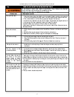
This manual includes color-coded safety messages that clarify instructions and specify areas where potential hazard exists. To 

prevent the possibility of equipment damage and serious injury or death, please observe strictly the instructions and warnings 

contained  in  the  messages.  If  warning  decals  become  damaged  or  missing,  replace  them  immediately. Avoid  accidents  by 

recognizing dangerous procedures or situations before they occur.

Serious injury or death will likely occur if the instructions are not 

followed.

Procedures marked IMPORTANT must be followed in order to prevent 

damage to machinery.

Serious injury or death may occur if the instructions are not followed. 

Instructions  marked  CAUTION  concern  safe  operating  procedure. 

Failure to comply may result in personal injury.

•  

DO NOT

 enter the pit area below the dock leveler.

•  

BEFORE BEGINNING ANY SERVICE PROCEDURES:


    – Disconnect the power and follow all LOCKOUT / TAGOUT procedures

•  Never operate a broken or damaged dock leveler. Have repairs done immediately by a qualified service technician.

•  Always secure and center loads on the forklifts. Loose or unbalanced loads are dangerous.

• The upper hinge point is a hazardous pinch point. Do not use fingers 

or hands to remove foreign materials.

•  Post

  safety  warnings  and  barricade  working  area 


at  dock level 

and  at  ground  level  to  prevent  unauthorized  use  of  the  leveler 

during maintenance/service.

 Never leave the dock leveler unattended in the raised position.

• Always make sure that the lip is seated inside the lip keepers after 

putting the dock in the parked position.

• Never leave loads sitting on the dock leveler.

• Do not attempt to raise the dock leveler if someone is standing on it.

• Do not use the dock leveler if the lip’s full width is not fully supported 

by the vehicle load bed.

• Do not operate the dock leveler beyond its rated capacity.

• 

DO NOT

 drive or walk onto the truck until it is parked against  the 

dock bumpers and the wheels are chocked, or the vehicle restraint 

has  been  fully  engaged.

• 

NEVER

  attempt  to  lift  or  hold  the  lip  out  by  hand.  Serious 

personal injury could occur.

• 

ALWAYS 

check  the  rigging  to  make  sure  that  it  is  secure  before 

proceeding  to lift  the  unit. 

Never  stand  under  any  unit  being 

lifted.

• 

NEVER

  remove  the  wheel  chocks  until  loading/  unloading  is 

finished and the truck driver has been given permission to depart.

• 

DO  NOT

  ground  welding  equipment  to  any  electrical components.

• 

DO NOT

 attach welder as ground to leveler platform when welding 

on  base  frame  assembly.  Attach  welder  ground  to  base  frame 

assembly 

only

• 

DO NOT

 allow the drill to go too deeply when drilling holes  in  the 

control  box.  Damage  to  the  control  systems  may occur.

• 

NEVER

 use air to blow debris from control box. Use a vacuum to 

remove debris from control box. 

• 

DO NOT

 connect green ground lead into control box or junction box 

until all welding has been completed.

• Always keep the work area clean and free of litter.

• Always clean all side openings of dirt and debris.

• Always clean all dirt and debris fron the lip hinge.

• Always clean up dry and liquid spills immediately after they occur. 

• Always maintain proper lighting in the work area.

  If  a  procedure  is  not  clearly  defined  in  this  manual,  contact  your 

authorized Service Representative. 

• 

ONLY TRAINED PERSONNEL 

should operate or service this equipment.

• 

DO NOT

 operate leveler until freight carrier is parked against the dock bumpers and has been secured by a vehicle restraint and/or chocks.

• 

ALWAYS

 return the leveler platform to the proper stored position.  

• 

ALWAYS

 conduct routine inspections and maintenance. Failure to conduct could cause personal injury or damage to equipment.

U-SERIES AIRBAG DOCK LEVELER with SINGLE PUSH BUTTON CONTROLS

 
3

Summary of Contents for U-Series

Page 1: ...ENTIRE CONTENTS OF THIS MANUAL FAILURE TO DO SO MAY RESULT IN PROPERTY DAMAGE BODILY INJURY OR DEATH INSTALLATION OWNER S MANUAL U SERIES AIRBAG DOCK LEVELER with SINGLE PUSH BUTTON CONTROLS U Series Airbag Dock Leveler with Single Push Button Controls Issue Date 07 07 2010 Rev 0 Part 038 747E ...

Page 2: ...NOTES ...

Page 3: ...NSTRUCTIONS 8 7 1 Functional Description 8 7 2 Deploying the Dock Leveler 8 7 3 Storing the Dock Leveler 8 7 4 Below Level End Loading 8 8 MAINTENANCE 9 8 1 Planned Maintenance 9 8 2 Operator Daily Inspection 9 8 3 Routine Servicing and Maintenance 9 8 4 Planned Maintenance Intervals 9 8 5 Maintenance Sequence 9 8 6 PM Checklist Dock Equipment 10 9 DOCK GENERAL ASSEMBLY COMPONENTS 6 DOCK 11 10 DOC...

Page 4: ...perates safely and efficiently under the toughest conditions temperature extremes heavy usage and exposure to caustic substances The deck flexes under load to allow a smooth cross docking transition minimizing the risk of worker injury and cargo or equipment damage The fall safe system provides additional protection by limiting platform free fall The manufacturer offers a full line of dock leveler...

Page 5: ...e is not subject to compensation The manufacturer reserves the right to make changes at any time to the modules components and accessories concurrent with its continuing product development program Specifications operating instructions and illustrations included in this manual are subject to change without notice Please contact manufacturer for the latest information MANUFACTURER S NOTE The Dock L...

Page 6: ...he dock leveler if the lip s full width is not fully supported by the vehicle load bed Do not operate the dock leveler beyond its rated capacity DO NOT drive or walk onto the truck until it is parked against the dock bumpers and the wheels are chocked or the vehicle restraint has been fully engaged NEVER attempt to lift or hold the lip out by hand Serious personal injury could occur ALWAYS check t...

Page 7: ...e OFF position or disconnected from the energy source Blue Giant strongly recommends that only OSHA approved lockout devices be utilized The energy isolating device must bear a prominent warning tag indicating that work is being done on the equipment and the name of the authorized employee responsible for the lockout It is mandatory that tagout notices not be susceptible to deterioration or illegi...

Page 8: ...DOCK 1 RUN ONE 1 2 I D CONDUIT FROM THE CONTROL STATION TO THE BLOWER MOTOR JUNCTION BOX 2 RUN ONE 1 2 I D CONDUIT FROM THE CONTROL STATION TO THE PIT FOR FUTURE EXPANSION I E INTERLOCKS COMBOS ETC MINIMUM CONCRETE STRENGTH 3 000 P S I POWER WIRING SINGLE PUSH BUTTON CONTROL STATION MOUNTED ON DRIVERS SIDE MAIN POWER from fused disconnect MOTOR WIRING to Blower Motor 50 DO NOT WIRE HIGH AND LOW VO...

Page 9: ...of the pit should be equal Use caution when lifting or moving the leveler Do not attempt to lift without suitable hoisting equipment capable of lifting as much as 2 000 lbs 1 000 kg Follow all hoisting safety require ments 5 If the rear beam does not line up squarely with the rear curb angle use 3 x 6 75mm x 150mm shims of suitable thickness to fully support top rear and bottom rear of rear beam a...

Page 10: ...specified dock bumpers as required Do not use the dock leveler without bumpers as damage to both building and leveler may result 17 Mount the operations placard provided with these Instructions to the wall in plain view of dock leveler operations 1 Clean up the entire work area and apply touch up paint to all welds scratches and burns 2 Test operate the unit through several full cycles of operatio...

Page 11: ...nu ally Do not drive on the leveler unless the lip is securely on the truck bed and has a minimum of 4 100mm overlap on its surface Do not exceed 4 mph when driving over the dock leveler Do not drive over edges of the leveler and or dock bumper blocks bumpers blocks are not structural 1 Once loading or unloading has been completed press and hold the UP button again inflating the air bag until the ...

Page 12: ...enance issues Regular maintenance and care of the dock leveler is very important for cost and operation efficiency and more importantly operator safety A faulty dock leveler is a potential source of danger to the operator and to other personnel working near it As with all quality equipment keep the dock leveler in good operating condition by following the recommended schedule of maintenance Failur...

Page 13: ...ck Shelter Check Dock Leveler Structure Sub Frame Shim Lubricate Rear Hinges Pins Lubricate Dock Leveler Lip Hinge Structural Damage Check Lip Crown Check For Proper Operation Dock Bumpers Extensions Overhead Door Curb Angle Place Updated Service Sticker On Equipmen Safety Skirts Clean Up Of Dock Leveler Area COMMENTS REPAIRS RECOMMENDED Customer Tel SWO Location Cust Contact Date Inspected By 8 6...

Page 14: ...26 004177 26 004691 109 699 N A 26 004692 ABU66 6 35 18 26 005478 1 26 005538 1 26 004691 4 111 595 1 200 03461 1 26 004692 3 ABU6 6 30 18 26 004179 1 26 004177 1 26 004691 109 699 200 03461 1 26 004692 ABU66 6 35 20 26 005478 2 26 005538 2 26 004691 4 111 595 1 26 005615 26 004692 3 ABU6 6 30 20 26 004179 2 26 004177 2 26 004691 109 699 200 03461 1 26 004692 ABU66 6 40 16 26 005479 26 005538 26 0...

Page 15: ...2 3 8 Flat Washer 27 2 011 080 Socket Head Shoulder Screws UNRC 26 2 26 004824 CABLE ROLLER ASSY 25 1 011 545 Nylon Insert Locknuts 1 4 20 U S 24 1 010 003 CAP SCREW 1 4 20 X 2 HH 23 1 26 004689 F SAFE TILT HANDLE 22 1 017 012 TENSION SPRING 21 1 26 004687 FALL SAFE WLDM T 20 1 012 211 Flat Washers U S 19 1 165 9197 RUBBER BUMPER 18 3 013 012 Spring pin 17 2 011 508 Hex Nuts U S 16 4 010 040 CAP S...

Page 16: ...23 1 26 004687 FALL SAFE WLDM T 26 004687 22 3 012 211 Flat Washers U S 012 211 21 1 165 9197 RUBBER BUMPER 165 9197 20 2 105 882 Flat Washers U S 105 882 19 3 013 012 Spring pin 1 4 DIA X 2 LNG 18 2 011 508 Hex Nuts U S 011 508 17 4 010 040 CAP SCREW 3 8 16 X 1 1 2 HH GR 5 b491 0 375 UNC x 1 Gr 5 16 4 012 201 Lock Washers 3 8 HELICAL 012 201 15 4 012 212 Flat Washers U S 012 212 14 1 26 004530 3 ...

Page 17: ... 11 Item No Qty Part No Description 1 1 26 005483 Lower Platform Weld RH 2 1 26 004593 2 Pivot Pin 3 1 26 005390 Top Platform Weldment 4 2 013 127 3 16 dia spring pin x 1 50 5 1 26 005475 LH air bag 8 L Dock 6 1 26 004816 Keeper Bar 7 5 011 552 Nylon Insert Locknuts 3 18 16 U S 8 5 010 014 Cap Screw 3 18 x 1 1 2 HH ZC 9 10 012 252 3 8 Flat Washer 10 2 012 210 Flat Washers US 11 2 011 545 Nylon Ins...

Page 18: ...per Bar 6 5 011 552 Nylon Insert Locknuts 3 8 16 U S 7 5 010 014 Cap Screw 3 8 16 x 1 HH ZC 8 10 012 252 3 8 Flat Washer 9 2 012 210 Flat Washers U S 10 2 011 545 Nylon Insert Locknuts 20 U S 11 1 26 004981 1 Pipe 12 1 26 004981 Pipe 13 1 26 004821 Tee Coupling 14 1 26 004981 3 Pipe 15 1 26 004820 Flex Pipe Coupling 16 1 26 004827 17 1 035 743 Hose Clamp 2 Air Bags 18 1 26 005620 Blower Motor Asse...

Page 19: ... 26 004530 3 PIVOT PIN 1 22 000998 MAIN SPRING 1 Complements for the Fall Safe Assembly Part Description Qty Req d HARDWARE REQ D 26 004689 F SAFE TILT HANDLE 1 Qty X 1 each Part 010 003 CAP SCREW Part 011 545 LOCK NUT NYLON INSERT 26 004338 CABLE WITH BALL END 1 HARDWARE REQ D 26 004824 CABLE ROLLER ASSEMBLY 2 Qty X 2 Part 011 080 Screw Qty X 4 Part 012 212 Washer Qty X 2 Part 012 252 Washer Qty ...

Page 20: ...ecessary 3 Lift Assist spring may be disengaged Check and adjust as necessary The lip will not extend 1 Debris may be in the lip hinge Check the hinge and clean away any dirt or corrosion The lip remains in the extended position 1 Lip may be bent or damaged Apply lubrication and if necessary replace the lip 2 The lip deployment mechanism may be damaged Conduct any necessary repairs or replace the ...

Page 21: ...NOTES U SERIES AIRBAG DOCK LEVELER with SINGLE PUSH BUTTON CONTROLS 18 ...

Page 22: ...NOTES U SERIES AIRBAG DOCK LEVELER with SINGLE PUSH BUTTON CONTROLS 19 ...

Page 23: ...NOTES U SERIES AIRBAG DOCK LEVELER with SINGLE PUSH BUTTON CONTROLS 20 ...

Page 24: ...rio Canada L6W 3K2 Phone 905 457 3900 Fax 905 457 2313 www BlueGiant com B L U E G I A N T E Q U I P M E N T C O R P O R A T I O N 2012 Blue Giant Equipment Corporation if calling within North America Phone 1 800 668 7078 Fax 1 888 378 5781 ...

Reviews: