background image

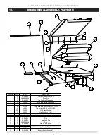
6.                          DOCK LEVELER INSTALLATION INSTRUCTIONS
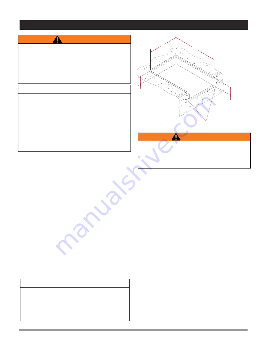


LENGTH

PIT MUST BE

KEPT SQUARE

WIDTH

DOCK BUMPERS

Typically 

 24” (609mm).

Typically 

23 1/2”(595mm)

Figure 1 : Pit Layout - Typical (Six piece curb angle shown)

!

IMPORTANT

!

Do not install, operate and/or service this leveler until you 

have  read  and  understood  all  of  the  safety  information 

and instructions contained herein and on the leveler.
Do  not  work  under  or  around  leveler  being  installed 

without  first  placing  adequate  barriers  to  positively 

prevent vehicle traffic from entering the work area.
Keep hands and feet clear of dock leveler pinch points.



!

The information below is crucial to proper installation:
Pit Curb Angles

A. Must be level side-to-side and front-to-back.

B. Must be square at both rear corners.

C. Side curb angles must be parallel to each other.

D. Finished floor to be flush with top surface of curb angle.
The leveler must be welded to a firmly embedded steel or other 

dock  steel  as  described  in  the  installation instructions. 

Do not attempt to use only bolts or anchors, to attach the dock 

leveler to the concrete.

1. 

Prior  to  installation,  clean  pit  thoroughly  and  verify  that  all 

dimensions  are  in  accordance  with  manufacturer  specifica-

tions.

2.

  Measure  height  of  rear  corners  of  dock  leveler,  bottom  of 

frame to top of deck plate, typically 23” (585mm). Measure 

depth of pit at both rear corners where rear bottom corners of 

frame will be positioned. Locate and place suitable shims (not 

supplied)  in  pit  corners  to  produce  a  depth  to  match  frame 

height. 

3.

 Measure height of dock leveler front corners, bottom of frame 

to  top  of  deck  plate,  typically  23-1/2”  (595mm).  Measure 

depth of pit at both front corners where front bottom corners of 

frame will be positioned. Locate and place suitable shims (not 

supplied) at both front corners to produce a depth to match 

frame height. See Figure 1.

!



4. 

Using slings that are rated for a minimum capacity of 2,000 lbs 

(1,000 kg), carefully sling the dock leveler into place squarely 

above the pit and lower it gently onto the pre-located shims. 

Position  the  leveler  to  best  suit  the  pit  and  the  dock  face. 

Space  between  the  sides  of  the  deck  and  sides  of  the  pit 

should be equal.

Use  caution  when  lifting  or  moving  the  leveler.  Do  not attempt 

to  lift  without  suitable  hoisting  equipment  capable  of  lifting  as 

much as 2,000 lbs (1,000 kg). Follow  all  hoisting safety require-

ments.

5.

 If the rear beam does not line up squarely with the rear curb 

angle,  use  3”  x  6”  (75mm  x  150mm)  shims  of  suitable 

thickness to fully  support  top  rear  and  bottom  rear  of  rear 

beam at weld areas. 


6. 

Remove and discard the shipping bolt from the front of the lip 

plate.  

7. 

There are two options for raising the deck to enable access to 

the blower motor for electrical hookup. 

     A) Prepare to hook up electrical wires to establish a temporary 

electrical hookup to enable the deck to be raised. 

    B) Use sling brackets and chains to raise the deck and allow 

access to the blower motor for electrical hookup.

8.

 Use the maintenance strut to engage the headboard and lip 

and hold the deck and lip in the raised, extended position.

9.

 Complete proper electrical hookup to blower motor.

10.

 Locate and place adequate and appropriate spacer shims to 

completely fill the space between the curb angle and frame at 

the following locations under the front frame:

A)  Under  the  maintenance  strut  base  mounting  bracket 

between the curb angle and frame.

B) Under the lip keeper brackets (one at each side of frame) 

between the curb angle and the frame.

C) Under the center point of the front frame between the curb 

angle and the frame.

11.

 After all electrical connections have been properly completed, 

press and hold the UP ‘I’ button until the deck has raised high 

enough  to  allow  successful  disengagement  of  the 

maintenance strut.  Release the button and allow the deck to 

lower  to  the  stored  position.  Ensure  that  the  lip  is  parked 

inside the lip keepers.

12.

 Adjust the height of all front shims as required to level the front 

sides of the deck with the pit curb angles. Tack-weld the front 

shims together as well as to the dock leveler frame and the pit 

curb angle.

IMPORTANT

It  is  important  that  the  shims  fill  the  space  between  the 

bottom edge of the back beam and face of the curb angle, as 

well as behind each hinge lug on the top edge. Confirm that 

the top of the back beam is flush with the top surface of the 

rear  curb  angle,  and  then  finish  weld  back  beam  to  curb 

angle.

U-SERIES AIRBAG DOCK LEVELER with SINGLE PUSH BUTTON CONTROLS

 
6

Summary of Contents for U-Series

Page 1: ...ENTIRE CONTENTS OF THIS MANUAL FAILURE TO DO SO MAY RESULT IN PROPERTY DAMAGE BODILY INJURY OR DEATH INSTALLATION OWNER S MANUAL U SERIES AIRBAG DOCK LEVELER with SINGLE PUSH BUTTON CONTROLS U Series Airbag Dock Leveler with Single Push Button Controls Issue Date 07 07 2010 Rev 0 Part 038 747E ...

Page 2: ...NOTES ...

Page 3: ...NSTRUCTIONS 8 7 1 Functional Description 8 7 2 Deploying the Dock Leveler 8 7 3 Storing the Dock Leveler 8 7 4 Below Level End Loading 8 8 MAINTENANCE 9 8 1 Planned Maintenance 9 8 2 Operator Daily Inspection 9 8 3 Routine Servicing and Maintenance 9 8 4 Planned Maintenance Intervals 9 8 5 Maintenance Sequence 9 8 6 PM Checklist Dock Equipment 10 9 DOCK GENERAL ASSEMBLY COMPONENTS 6 DOCK 11 10 DOC...

Page 4: ...perates safely and efficiently under the toughest conditions temperature extremes heavy usage and exposure to caustic substances The deck flexes under load to allow a smooth cross docking transition minimizing the risk of worker injury and cargo or equipment damage The fall safe system provides additional protection by limiting platform free fall The manufacturer offers a full line of dock leveler...

Page 5: ...e is not subject to compensation The manufacturer reserves the right to make changes at any time to the modules components and accessories concurrent with its continuing product development program Specifications operating instructions and illustrations included in this manual are subject to change without notice Please contact manufacturer for the latest information MANUFACTURER S NOTE The Dock L...

Page 6: ...he dock leveler if the lip s full width is not fully supported by the vehicle load bed Do not operate the dock leveler beyond its rated capacity DO NOT drive or walk onto the truck until it is parked against the dock bumpers and the wheels are chocked or the vehicle restraint has been fully engaged NEVER attempt to lift or hold the lip out by hand Serious personal injury could occur ALWAYS check t...

Page 7: ...e OFF position or disconnected from the energy source Blue Giant strongly recommends that only OSHA approved lockout devices be utilized The energy isolating device must bear a prominent warning tag indicating that work is being done on the equipment and the name of the authorized employee responsible for the lockout It is mandatory that tagout notices not be susceptible to deterioration or illegi...

Page 8: ...DOCK 1 RUN ONE 1 2 I D CONDUIT FROM THE CONTROL STATION TO THE BLOWER MOTOR JUNCTION BOX 2 RUN ONE 1 2 I D CONDUIT FROM THE CONTROL STATION TO THE PIT FOR FUTURE EXPANSION I E INTERLOCKS COMBOS ETC MINIMUM CONCRETE STRENGTH 3 000 P S I POWER WIRING SINGLE PUSH BUTTON CONTROL STATION MOUNTED ON DRIVERS SIDE MAIN POWER from fused disconnect MOTOR WIRING to Blower Motor 50 DO NOT WIRE HIGH AND LOW VO...

Page 9: ...of the pit should be equal Use caution when lifting or moving the leveler Do not attempt to lift without suitable hoisting equipment capable of lifting as much as 2 000 lbs 1 000 kg Follow all hoisting safety require ments 5 If the rear beam does not line up squarely with the rear curb angle use 3 x 6 75mm x 150mm shims of suitable thickness to fully support top rear and bottom rear of rear beam a...

Page 10: ...specified dock bumpers as required Do not use the dock leveler without bumpers as damage to both building and leveler may result 17 Mount the operations placard provided with these Instructions to the wall in plain view of dock leveler operations 1 Clean up the entire work area and apply touch up paint to all welds scratches and burns 2 Test operate the unit through several full cycles of operatio...

Page 11: ...nu ally Do not drive on the leveler unless the lip is securely on the truck bed and has a minimum of 4 100mm overlap on its surface Do not exceed 4 mph when driving over the dock leveler Do not drive over edges of the leveler and or dock bumper blocks bumpers blocks are not structural 1 Once loading or unloading has been completed press and hold the UP button again inflating the air bag until the ...

Page 12: ...enance issues Regular maintenance and care of the dock leveler is very important for cost and operation efficiency and more importantly operator safety A faulty dock leveler is a potential source of danger to the operator and to other personnel working near it As with all quality equipment keep the dock leveler in good operating condition by following the recommended schedule of maintenance Failur...

Page 13: ...ck Shelter Check Dock Leveler Structure Sub Frame Shim Lubricate Rear Hinges Pins Lubricate Dock Leveler Lip Hinge Structural Damage Check Lip Crown Check For Proper Operation Dock Bumpers Extensions Overhead Door Curb Angle Place Updated Service Sticker On Equipmen Safety Skirts Clean Up Of Dock Leveler Area COMMENTS REPAIRS RECOMMENDED Customer Tel SWO Location Cust Contact Date Inspected By 8 6...

Page 14: ...26 004177 26 004691 109 699 N A 26 004692 ABU66 6 35 18 26 005478 1 26 005538 1 26 004691 4 111 595 1 200 03461 1 26 004692 3 ABU6 6 30 18 26 004179 1 26 004177 1 26 004691 109 699 200 03461 1 26 004692 ABU66 6 35 20 26 005478 2 26 005538 2 26 004691 4 111 595 1 26 005615 26 004692 3 ABU6 6 30 20 26 004179 2 26 004177 2 26 004691 109 699 200 03461 1 26 004692 ABU66 6 40 16 26 005479 26 005538 26 0...

Page 15: ...2 3 8 Flat Washer 27 2 011 080 Socket Head Shoulder Screws UNRC 26 2 26 004824 CABLE ROLLER ASSY 25 1 011 545 Nylon Insert Locknuts 1 4 20 U S 24 1 010 003 CAP SCREW 1 4 20 X 2 HH 23 1 26 004689 F SAFE TILT HANDLE 22 1 017 012 TENSION SPRING 21 1 26 004687 FALL SAFE WLDM T 20 1 012 211 Flat Washers U S 19 1 165 9197 RUBBER BUMPER 18 3 013 012 Spring pin 17 2 011 508 Hex Nuts U S 16 4 010 040 CAP S...

Page 16: ...23 1 26 004687 FALL SAFE WLDM T 26 004687 22 3 012 211 Flat Washers U S 012 211 21 1 165 9197 RUBBER BUMPER 165 9197 20 2 105 882 Flat Washers U S 105 882 19 3 013 012 Spring pin 1 4 DIA X 2 LNG 18 2 011 508 Hex Nuts U S 011 508 17 4 010 040 CAP SCREW 3 8 16 X 1 1 2 HH GR 5 b491 0 375 UNC x 1 Gr 5 16 4 012 201 Lock Washers 3 8 HELICAL 012 201 15 4 012 212 Flat Washers U S 012 212 14 1 26 004530 3 ...

Page 17: ... 11 Item No Qty Part No Description 1 1 26 005483 Lower Platform Weld RH 2 1 26 004593 2 Pivot Pin 3 1 26 005390 Top Platform Weldment 4 2 013 127 3 16 dia spring pin x 1 50 5 1 26 005475 LH air bag 8 L Dock 6 1 26 004816 Keeper Bar 7 5 011 552 Nylon Insert Locknuts 3 18 16 U S 8 5 010 014 Cap Screw 3 18 x 1 1 2 HH ZC 9 10 012 252 3 8 Flat Washer 10 2 012 210 Flat Washers US 11 2 011 545 Nylon Ins...

Page 18: ...per Bar 6 5 011 552 Nylon Insert Locknuts 3 8 16 U S 7 5 010 014 Cap Screw 3 8 16 x 1 HH ZC 8 10 012 252 3 8 Flat Washer 9 2 012 210 Flat Washers U S 10 2 011 545 Nylon Insert Locknuts 20 U S 11 1 26 004981 1 Pipe 12 1 26 004981 Pipe 13 1 26 004821 Tee Coupling 14 1 26 004981 3 Pipe 15 1 26 004820 Flex Pipe Coupling 16 1 26 004827 17 1 035 743 Hose Clamp 2 Air Bags 18 1 26 005620 Blower Motor Asse...

Page 19: ... 26 004530 3 PIVOT PIN 1 22 000998 MAIN SPRING 1 Complements for the Fall Safe Assembly Part Description Qty Req d HARDWARE REQ D 26 004689 F SAFE TILT HANDLE 1 Qty X 1 each Part 010 003 CAP SCREW Part 011 545 LOCK NUT NYLON INSERT 26 004338 CABLE WITH BALL END 1 HARDWARE REQ D 26 004824 CABLE ROLLER ASSEMBLY 2 Qty X 2 Part 011 080 Screw Qty X 4 Part 012 212 Washer Qty X 2 Part 012 252 Washer Qty ...

Page 20: ...ecessary 3 Lift Assist spring may be disengaged Check and adjust as necessary The lip will not extend 1 Debris may be in the lip hinge Check the hinge and clean away any dirt or corrosion The lip remains in the extended position 1 Lip may be bent or damaged Apply lubrication and if necessary replace the lip 2 The lip deployment mechanism may be damaged Conduct any necessary repairs or replace the ...

Page 21: ...NOTES U SERIES AIRBAG DOCK LEVELER with SINGLE PUSH BUTTON CONTROLS 18 ...

Page 22: ...NOTES U SERIES AIRBAG DOCK LEVELER with SINGLE PUSH BUTTON CONTROLS 19 ...

Page 23: ...NOTES U SERIES AIRBAG DOCK LEVELER with SINGLE PUSH BUTTON CONTROLS 20 ...

Page 24: ...rio Canada L6W 3K2 Phone 905 457 3900 Fax 905 457 2313 www BlueGiant com B L U E G I A N T E Q U I P M E N T C O R P O R A T I O N 2012 Blue Giant Equipment Corporation if calling within North America Phone 1 800 668 7078 Fax 1 888 378 5781 ...

Reviews: