background image

12

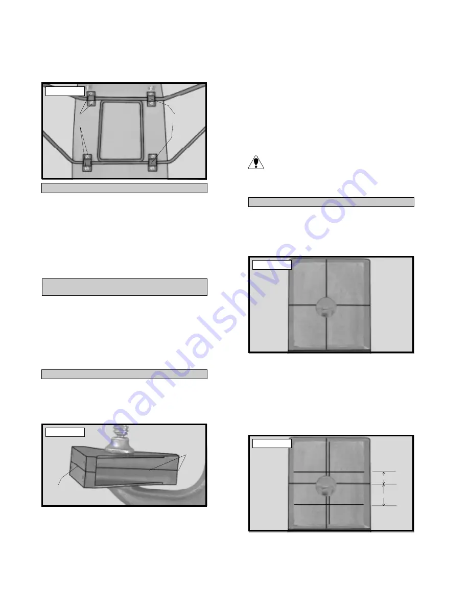
o

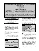
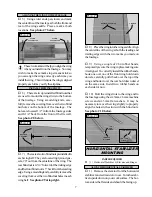
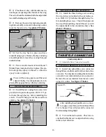
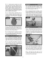
6) Secure the gear assembly in place by in-

stalling the eight 3mm x 12mm wood screws
through the mounting straps and remove the
masking tape.  See photo # 20 below.

Photo # 20

INSTALLING THE MAIN GEAR WHEELS

o

7) Slide one nylon spacer onto each axle.

Slide one 127mm diameter wire spoke wheel onto
each axle and up against the nylon spacers.  Se-
cure the wheels in place by sliding one wheel col-
lar onto each axle and up against the wheels.
Tighten the 3mm x 6mm machine screw in the
wheel collars.  The wheels should be able to ro-
tate without binding.

PARTS REQUIRED

ENGINE MOUNTING

MOUNTING ENGINE TO MOTOR MOUNT

o

{2} Nylon Motor Mount Beams

o

{4} 3mm x 20mm Machine Screws

o

{4} 3mm x 25mm Machine Screws

o

{12}3mm Flat Washers

o

{4} 3mm Lock Nuts

o

{4} 3mm Blind Nuts

o

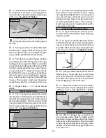
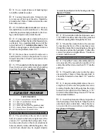
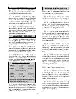
1) Using a clamp or a vise, align the two motor

mount beams and clamp them together.  The beam
halves are universal and the webbing should face
the outside edges.  See photo # 21 below.

Photo # 21

o

2) Mark the locations of the four engine

mounting holes on the beams using a pencil.  For
the engine to align properly, it is important that
the front edge of the engine's drive washer be
3-3/4” forward from the rear edge of the mount-
ing beams.

o

3) When satisfied with the alignment of the

engine, remove the beams from the clamp and
drill 1/8” holes through the mounting beams at
the four engine mounting hole locations.

o

4) Mount the engine to the mounting beams

using the four 3mm x 25mm machine screws, eight
3mm flat washers and four 3mm lock nuts.  Tighten
the screws and nuts completely.

If using an engine equipped with a remote
needle valve we recommend mounting the

needle valve to the engine prior to installing the
engine on the motor mount beams.

ALIGNING THE MOTOR MOUNT

o

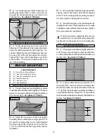
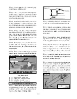
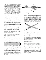
5) The engine is mounted upright on the fire-

wall.  Using a ruler and a pen, measure and draw
a vertical centerline and a horizontal centerline on
the firewall.  See photo # 22 below.

Photo # 22

o

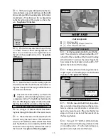
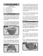
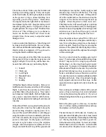
6) Using a ruler and a pen, measure 1/8” to

the right of the vertical centerline (looking at the
firewall) and draw a second vertical line.  Measure
1/2” up from the horizontal centerline and draw a
second horizontal line.  Measure 7/8” down from
the horizontal centerline and draw a third horizon-
tal line.  See photo # 23 below.

Photo # 23

MOUNTING

STRAPS

3mm x10mm

WOOD SCREWS

ALIGN
EDGES

ALIGN
EDGES

1/2”

7/8”

Summary of Contents for Global Arf

Page 1: ...and open framework capture a more experi mental time in aviation The high lift wing and generous wing area mean super slow stall speed and very forgiving flight characteristics Don t be sur prised if...

Page 2: ...the Horizontal Stabilizer 7 Vertical Stabilizer Mounting 8 Align the Vertical Stabilizer 8 Mounting the Vertical Stabilizer 8 Control Surface Installation 8 Hinge the Ailerons 8 Hinge the Elevator 9 I...

Page 3: ...o 1 Wire Main Gear Assembly o 1 Wire Nose Skid o 2 Nylon Mounting Straps w 4mm Slot o 5 Nylon Mounting Straps w 3mm Slot o 2 127mm Diameter Wire Spoke Wheels o 2 Nylon Axle Spacers o 2 Wheel Collars w...

Page 4: ...o MaskingTape o Paper Towels o RubbingAlcohol FIELD SUPPORT EQUIPMENT NEEDED o Magnum12VElectricStarter 361006 o Magnum 12V Fuel Pump 237377 o Magnum Locking Glow Clip 237440 o Global 12V Battery 1101...

Page 5: ...2 Wing Halves w Ailerons and Hinges o 1 Forward Dihedral Brace W 40 o 1 Rear Dihedral Brace W 41 o 1 Look at the face of each root rib on both winghalves Noticehowtheexcesscoveringma terialoverlapson...

Page 6: ...and rubbing alcohol Allow the epoxy to cure before pro ceeding See photo 3 below Photo 4 Photo 3 PARTSREQUIRED WING MOUNTING INSTALLTHEWINGHOLDDOWNDOWELS o 1 Fuselage o 2 Wing Hold Down Dowels W 43 o...

Page 7: ...owels carefully pull it back over the top of the wing and hook it over the rear hold down dowel on the same side Install two rubber bands on each side for now o 10 Bolt the wing struts to the wing and...

Page 8: ...izontal stabilizerwiththewing Whenviewedfromthe rear thehorizontalstabilizershouldbelevelwith the wing If it is not level use sandpaper and sand down the high side of the stabilizer mount ingplatformu...

Page 9: ...deedgesoftheverticalstabilizermountingslot inthehorizontalstabilizer Usingamodelingknife carefullyremovethiscoveringalso Thiswillhelp insureagoodgluejoint o 4 Set the vertical stabilizer back in place...

Page 10: ...an 1 32 See photo 16 below Photo 16 o 7 With the elevator tight against the stabi lizer rotate the elevator down about 45 Apply sixdropsofKwikBondThinC Atotheexposed area of each hinge Allow the glue...

Page 11: ...ding PARTSREQUIRED MAIN LANDING GEAR ALIGNINGTHEMAINGEARASSEMBLY o 1 Wire Main Gear Assembly o 2 Nylon Mounting Straps w 4mm Slot o 2 Nylon Mounting Straps w 3mm Slot o 2 Nylon Axle Spacers o 2 Wheel...

Page 12: ...to align properly it is important that the front edge of the engine s drive washer be 3 3 4 forward from the rear edge of the mount ingbeams o 3 Whensatisfiedwiththealignmentofthe engine remove the b...

Page 13: ...flatwashersandfour3mmblind nuts Tightenthescrewscompletelyuntiltheblind nuts have been completely seated in the back of the firewall See photo 26 at top right Photo 26 PARTSREQUIRED NOSE SKID ALIGNTHE...

Page 14: ...pper assembly in place the weightedpickupshouldbeabout3 8 awayfrom the rear of the tank and move freely inside the tank The vent tube should be just below the top of the tank but not rub against the t...

Page 15: ...s in the servo tray Because the size of servos differ you may need to adjust the size of the precut open ings Youmayalsoneedtouseamodelingknife andcutagroovetoallowroomfortheservowires o 2 Remove the...

Page 16: ...elow Photo 34 INSTALLINGTHEFUSELAGESERVOS o 13 Install the three fuselage servos using the wood screws provided with your radio sys tem Drill 1 16 pilot holes through the tray be foreinstallingthescre...

Page 17: ...r looking from behind 1 3 8 up from the bottom of the rudder Position the control horn so the clevis attachmentholesaredirectlyin linewiththehinge line Thecontrolhornshouldalsobeparallelwith the hinge...

Page 18: ...from the fuselage side Posi tion the control horn so the clevis attachment holesaredirectlyin linewiththehingeline The control horn should also be angled slightly Figure 7 o 2 Whensatisfiedwiththeali...

Page 19: ...ble Control Horns INSTALLINGTHEAILERONLINKAGE o 1 Threadonenylonadjustablecontrolhorn onto each aileron torque rod Thread them on until they are 7 8 above the bottom surface of the wing See figure 8 a...

Page 20: ...ere the pushrod tubes contact it on either side Remove the seat back and cut out only those areas that interfere with the push rod tubes Test fit the seat back once more and make any further adjustmen...

Page 21: ...ebeforeproceeding o 16 Using 220 grit sandpaper roughen the bottomofthebarrelseatback UsingKwikBond Thick C A glue the seat back to the top of the barrel seat See photo 46 below Photo 46 o 17 Roughent...

Page 22: ...tall the propeller recommended for yourengineandsecureitinplaceusingtheafter marketspinnernutthatyoupurchasedseparately o 1 It is critical that your airplane be bal anced correctly Improper balance wi...

Page 23: ...sitionoftheclevisatthe controlhorntowardtheoutermosthole youwill decreasetheamountofthrowofthatcontrolsur face Movingtheclevistowardthecontrolsurface willincreasetheamountofthrow FLIGHT PREPARATION o...

Page 24: ...egin you should know how your Blue Max operates First there are four forces operating onaflyingaircraft Lift Weight ThrustandDrag Theenginewillcreatethrusttoovercomethedrag Intimeswhentheengineisoff g...

Page 25: ...f the ground and theairplaneismovingfast Gentlyapplyasmall amount of up elevator to lift the nose The wing willlifttheplaneofftheground Atthispointlet off of the rudder and use the ailerons to keep th...

Page 26: ...talldoes occur allow the nose to drop which will in crease the airspeed then apply up elevator to level theplane Remembertonotpulltoo muchupelevatororthestallmayoccuragain 2 Radical Turns Keeping the...

Page 27: ...___________________ 11 How does this kit compare to similar kits byothermanufacturers o BetterThan o As Good o Not as Good 12 Please listanyothercommentsor suggestionsyouhave _________________________...

Page 28: ...28 Fold along dotted line Fold along dotted line Place Stamp Here GlobalHobbyDistributors Attn CustomerServiceDepartment 18480BandilierCircle Fountain Valley CA 92728...

Reviews: