15
o
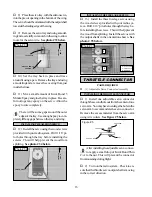
10) Secure the fuel tank in place using sev-
eral pieces of foam rubber. Seal any gaps be-
tween the stopper assembly and the firewall us-
ing silicon sealer. Be careful not to get any sealer
inside the aluminum tubing.
PARTS REQUIRED
THROTTLE LINKAGE
INSTALLING THE THROTTLE LINKAGE
o
{1} 1.5mm x 300mm Wire Threaded One End
o
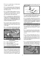
1) Locate and drill a 3/32” hole through the
firewall for the throttle pushrod wire to pass
through (you may need to temporarily remove the
engine). The hole should be level with the throttle
arm, but may need to be moved slightly to clear
the fuel tank depending on the engine used.
o
2) Slide the plain end of the pushrod wire
through the hole and into the fuselage. Remove
the throttle arm from the carburetor and attach
the Z-bend to the outer hole in the arm.
o
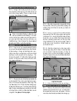
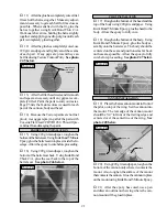
3) Reattach the throttle arm to the carbure-
tor and use a pair of pliers to make any necessary
bends in the wire so it does not bind when the
carburetor is moved from idle to the full throttle
position. See photo # 30 below.
Photo # 30
PARTS REQUIRED
SERVO INSTALLATION
INSTALLING THE FUSELAGE SERVO TRAY
o
{1} Aileron Servo Tray (W-39)
o
{1} Fuselage Servo Tray (D-47)
o
{4} 3mm x 12mm Wood Screws
o
1) Install the rubber grommets and brass
collets onto three servos. Test fit the servos into
the precut servo holes in the servo tray.
Because the size of servos differ, you may
need to adjust the size of the precut open-
ings. You may also need to use a modeling knife
and cut a groove to allow room for the servo wires.
o
2) Remove the servos from the servo tray.
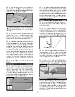
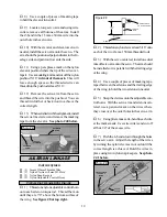
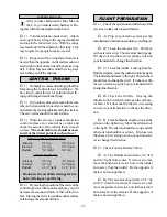
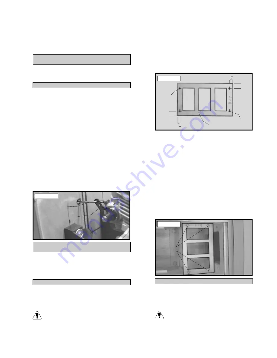
Using a ruler and a pen, locate and mark the po-
sition of the four servo tray mounting holes on the
top of the tray. Two holes are located 3/8” back
from the front edge of the tray and 1/8” in from
each side. Two holes are also located 3/8” for-
ward of the rear edge and 1/8” in from the sides.
See photo # 31 below.
Photo # 31
o
3) Using a 1/16” drill bit, drill pilot holes
through the servo tray at the four mounting hole
locations.
o
4) Set the servo tray onto the preinstalled
support rails just to the rear of the forward bulk-
head. The front of the tray should be pushed
firmly up against the forward bulkhead.
o
5) Using a 1/16” drill bit and the pilot holes
in the servo tray as a guide, drill four holes through
the support rails.
o
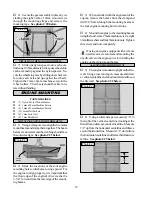
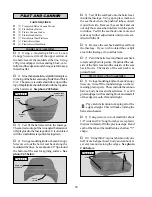
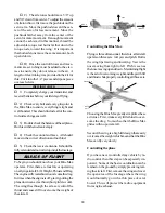
6) Secure the tray in place using four 3mm x
12mm wood screws. See photo # 32 below.
Photo # 32
INSTALLING THE AILERON SERVO TRAY
o
7) Install the rubber grommets and brass
collets onto the fourth servo. Test fit the servo
into the aileron servo tray (W-39).
Because the size of servos differ, you may
need to adjust the size of the precut open-
ings. You may also need to use a modeling knife
and cut a groove to allow room for the servo wire.
PUSHROD
WIRE
THROTTLE
ARM
3/8”
1/8”
3/8”
1/8”
MAKE
MARKS
MAKE
MARKS
SERVO TRAY
3mm x 12mm
WOOD
SCREWS

