16
o
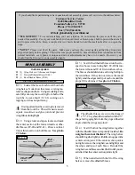
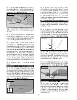
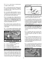
8) Place the servo tray, with the aileron servo,
into the precut opening in the bottom of the wing.
The servo should be orientated with the output shaft
towards the trailing edge of the wing.
o
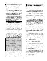
9) Remove the servo tray and using a model-
ing knife, carefully cut a notch in the wing to allow
room for the servo wire. See photo # 33 below.
Photo # 33
o
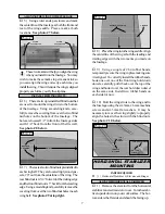
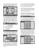
10) Set the tray back in place and trace
around it using a pen. Remove the tray and using
a modeling knife, remove the covering from just
inside the lines.
o
11) Mix a small amount of Kwik Bond 5
Minute Epoxy and glue the tray in place. Be care-
ful not to get any epoxy on the servo. Allow the
epoxy to cure completely.
There will be some gaps around the outer
edges of the tray. Use enough epoxy to com-
pletely fill any gaps between the tray and wing.
INSTALLING THE AILERON SERVO
o
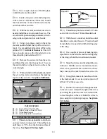
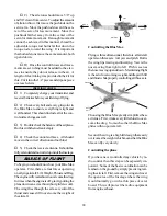
12) Install the servo using the wood screws
provided with your radio system. Drill 1/16” pi-
lot holes through the tray before installing the
screws. This will help prevent the wood from
splitting. See photo # 34 below.
Photo # 34
INSTALLING THE FUSELAGE SERVOS
o
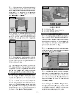
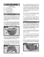
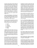
13) Install the three fuselage servos using
the wood screws provided with your radio sys-
tem. Drill 1/16” pilot holes through the tray be-
fore installing the screws. This will help prevent
the wood from splitting. Install the servos with
the output shafts in the orientation shown. See
photo # 35 below.
Photo # 35
PARTS REQUIRED
THROTTLE CONNECTOR
INSTALLING THE THROTTLE CONNECTOR
o
{1} Adjustable Servo Connector Assembly
o
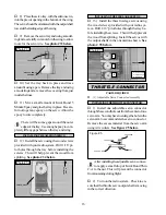
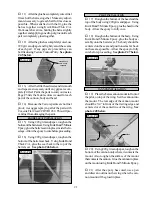
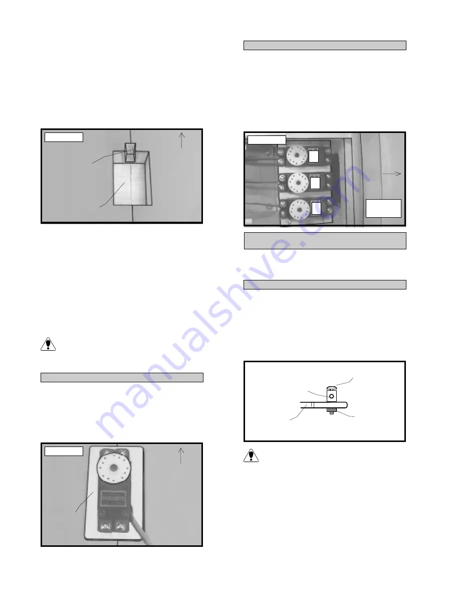
1) Install one adjustable servo connector
through the second hole out from the center of one
servo arm. You may have to enlarge the hole in the
servo arm to accommodate the servo connector.
Remove the excess material from the servo arm
using wire cutters. See figure # 5 below.
Figure # 5
After installing the adjustable servo connec-
tor apply a small drop of Kwik Bond Thin
C/A to the nut. This will prevent the connector
from loosening during flight.
o
2) Turn on the radio system. Check to en-
sure that the throttle servo output shaft is moving
in the correct direction.
CUT NOTCH
PRECUT SERVO
OPENING
SERVO TRAY
TRAILING
EDGE
TRAILING
EDGE
T
R
E
E = ELEVATOR
T = THROTTLE
R = RUDDER
SERVO ARM
NUT
SET SCREW
CONNECTOR
FRONT

