18
o
8) Use a couple of pieces of masking tape
to hold the rudder in neutral.
o
9) Locate a long servo arm. Using wire cut-
ters, remove all but one of the arms. Install the
Z-bend in the 1.5mm x 50mm wire into the outer
hole in the servo arm.
o
10) With the rudder and rudder servo in neu-
tral, install the servo arm onto the servo. The arm
should be positioned perpendicular to the fuse-
lage side and point out towards the side.
o
11) Using a pen, place a mark on the nylon
rudder pushrod where the tip of the threaded wire
overlaps it. Use a modeling knife and cut off the
nylon pushrod 5/16” in front of the mark. This
will leave enough space so the threaded wire can
thread into the pushrod at least 5/16”.
o
12) Remove the servo arm from the servo
and thread the wire into the pushrod. You can
thread it in further or back it out to achieve the
correct length.
o
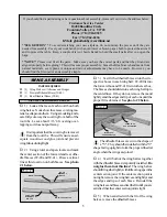
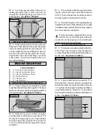
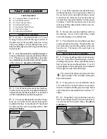
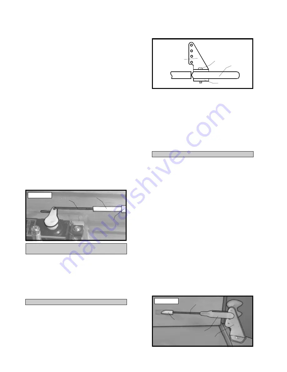
13) When satisfied with the alignment, install
the servo arm set screw and remove the masking
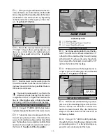
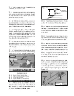
tape from the rudder. See photo # 38 below.
Photo # 38
PARTS REQUIRED
ELEVATOR PUSHROD
INSTALLING THE ELEVATOR CONTROL HORN
o
{1} Nylon Control Horn w/Nylon Back Plate
o
{2} 2mm x 15mm Machine Screws
o
{1} 990mm Nylon Pushrod
o
{1} 1.5mm x 45mm Wire Threaded Both Ends
o
{1} 1.5mm x 50mm Threaded Wire w/Z-Bend
o
{1} Nylon Clevis w/1.5mm I.D. Hole
o
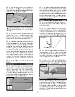
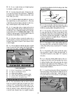
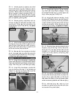
1) The centerline of the elevator control
horn is located on the bottom right side of the
elevator, 3/4” out from the fuselage side. Posi-
tion the control horn so the clevis attachment
holes are directly in-line with the hinge line. The
control horn should also be angled slightly
Figure # 7
o
2) When satisfied with the alignment, use a
3/32” drill bit and the control horn as a guide and
drill the mounting holes through the elevator.
o
3) Mount the control horn to the elevator
by inserting the 2mm x 15mm machine screws
through the control horn mounting base, through
the elevator and into the backplate. Tighten the
screws, but do not overtighten them. You do not
want to crush the wood.
o
4) Thread the 1.5mm x 45mm threaded wire
into one end of the second nylon pushrod. For
safety, thread the wire no less than 5/16” into the
pushrod.
o
5) Thread the nylon clevis onto the oppo-
site end of the 1.5mm x 45mm threaded wire. It
should be threaded no less than 5/16” onto the
wire also.
o
6) Using a modeling knife remove the cov-
ering from over the elevator pushrod exit slot.
Looking from the back of the airplane, the slot is
located on the right side of the fuselage, 1-7/8”
forward of the rudder hinge line and 1/2” below
the horizontal stabilizer.
o
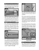
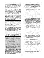
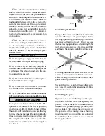
7) Insert the plain end of the nylon pushrod
into the fuselage from the back. Snap the clevis
onto the elevator control horn. Move the eleva-
tor up and down to ensure there is no binding.
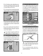
See photo # 39 below.
INSTALLING THE ELEVATOR PUSHROD
Photo # 39
PUSHROD
WIRE
NYLON
PUSHROD
PUSHROD
TUBE
towards the pushrod exit in the fuselage side. See
figure # 7 below.
NYLON
CLEVIS
PUSHROD
WIRE
NYLON
PUSHROD
CONTROL
HORN
CONTROL HORN
BACKPLATE
MACHINE
SCREW
ELEVATOR


