19
o
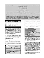
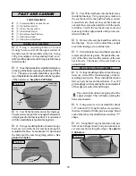
8) Use a couple of pieces of masking tape
to hold the elevator in neutral.
o
9) Locate a long servo arm and using wire
cutters, remove all but one of the arms. Install
the Z-bend in the 1.5mm x 50mm wire into the
outer hole in the servo arm.
o
10) With the elevator and elevator servo in
neutral, install the servo arm onto the servo. The
arm should be positioned perpendicular to the fu-
selage side and point out towards the side.
o
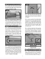
11) Using a pen, place a mark on the nylon
elevator pushrod where the tip of the wire over-
laps it. Use a modeling knife and cut off the nylon
pushrod 5/16” in front of the mark. This will
leave enough space so the threaded wire can
thread into the pushrod at least 5/16”.
o
12) Remove the servo arm from the servo
and thread the wire into the pushrod. You can
thread it in further or back it out to achieve the
correct length.
o
13) When satisfied with the alignment, install
the servo arm set screw and remove the masking
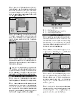
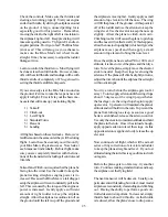
tape from the elevator. See photo # 40 below.
Photo # 40
PARTS REQUIRED
AILERON LINKAGE
o
{2} 2mm x 150mm Threaded Wire
o
{2} Nylon Clevises w/2mm I.D. Hole
o
{2} Nylon Snap Keepers
o
{2} Nylon Adjustable Control Horns
INSTALLING THE AILERON LINKAGE
o
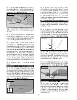
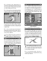
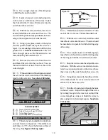
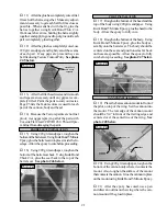
1) Thread one nylon adjustable control horn
onto each aileron torque rod. Thread them on
until they are 7/8” above the bottom surface of
the wing. See figure # 8 at top right.
Figure # 8
o
2) Thread one nylon clevis at least 5/16” onto
each of the two 2mm x 150mm threaded rods.
o
3) With the servo centered, install one dual
takeoff servo arm onto the servo. The arm should
be installed so it is parallel with the trailing edge
of the wing.
o
4) Use a couple of pieces of masking tape,
taped between the ailerons and the trailing edge
of the wing, to hold the two ailerons in neutral.
o
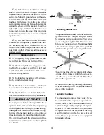
5) Snap the clevises onto the adjustable con-
trol horns. With the servo arm and ailerons cen-
tered, use a pen and mark on the wires where
they cross over the outer holes in the servo arm.
o
6) Using pliers, make an L-bend in each wire
at the marks made. Use wire cutters and cut off
all but 1/4” of the excess wire.
o
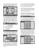
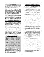
7) Push the L-bends down through the holes
in the servo arm. Adjust the length of the wires
by turning the nylon clevises in or out until the
correct length is achieved. Hold the wires in
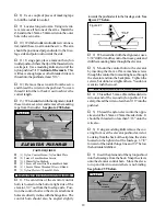
place using two nylon snap keepers. See photo
# 41 below.
Photo # 41
PUSHROD
WIRE
NYLON
PUSHROD
PUSHROD
TUBE
7/8”
PUSHROD
WIRE
NYLON
CLEVIS
ADJUSTABLE
CONTROL
HORN
SNAP KEEPER
ADJUSTABLE
CONTROL HORN
WING
TORQUE
ROD

