7
o
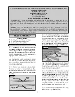
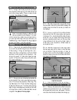
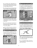
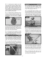
5) Using a ruler and a pen, locate and mark
the centerline of the fuselage at both the front and
rear of the wing saddle. Place a mark at both
locations. See photo # 7 below.
These two marks will help you align the wing
when you install it on the fuselage. You may
wish to make these marks in permanent ink so
you can align the wing correctly each time you
install the wing. This will ensure the wing is aligned
properly each time you fly the airplane.
o
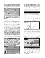
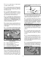
6) There are two preinstalled blind nuts that
are used to mount the wing struts to the bottom
of the fuselage. Using a modeling knife, care-
fully remove the covering from over the two blind
nut holes on the bottom of the fuselage. The
holes are located 1/2” in from the fuselage sides
and 8-1/4” back from the front of the firewall.
See photo # 8 below.
o
8) Place the wing into the wing saddle. Align
the centerline of the wing at both the leading and
trailing edges with the two marks you made on
the fuselage.
o
9) Using a couple of # 64 rubber bands,
temporarily secure the wing in place making sure
it is aligned. To correctly install the rubber bands,
hook one over one of the front wing hold down
dowels, carefully pull it back over the top of the
wing and hook it over the rear hold down dowel
on the same side. Install two rubber bands on
each side for now.
o
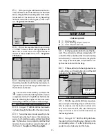
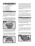
10) Bolt the wing struts to the wing and to
the fuselage using the six 3mm x 6mm machine
screws and six 3mm flat washers. It may be
necessary to move the wing slightly to properly
align the holes in the struts with the blind nuts.
See photo # 10 below.
ALIGNING THE WING TO THE FUSELAGE
Photo # 7
INSTALL THE WING STRUTS
Photo # 8
o
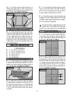
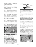
7) There are also two blind nuts preinstalled in
each wing half. They are located in plywood gus-
sets, 20” out from the centerline of the wing. The
rear blind nut is 2-3/4” forward of the trailing edge
and the front blind nut is 3” back from the leading
edge. Using a modeling knife, carefully remove the
covering from over the two blind nut holes in each
wing half. See photo # 9 at top right.
Photo # 9
Photo # 10
PARTS REQUIRED
HORIZONTAL STABILIZER
MOUNTING
ALIGN THE HORIZONTAL STABILIZER
o
{1} Horizontal Stabilizer w/Elevator and Hinges
o
1) Remove the elevator from the horizontal
stabilizer and set it aside for now. Turn the stabi-
lizer upside down on your work surface. The bot-
tom side is the flat side and should be facing up.
MARK
CENTERLINE
MARK
CENTERLINE
REMOVE
COVERING
8-1/4”
WING TIP
REMOVE COVERING
AILERON
3mm FLAT
WASHER
3mm x
6mm
SCREW
3mm x 6mm
SCREW
3mm FLATWASHER

