


8
ASSEMBLY INSTRUCTIONS
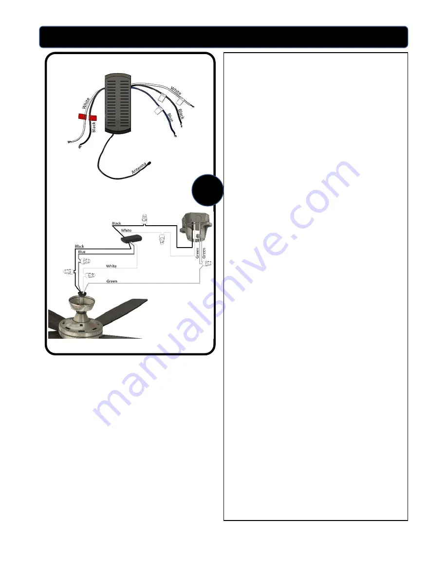
8.
Use the supplied wire connectors to connect
the fan wires to the remote receiver and
then the receiver to the power supply wires
according to the wiring diagram and
following instructions:
Connecting the fan to the remote receiver:
•
Connect the white wire from the fan to the
white (common) wire from the 3-wire side
of the receiver.
•
Connect the black wire from the fan to the
black wire from the 3-wire side of the
receiver.
•
Connect the blue wire from the fan to the
blue wire from the 3-wire side of the
receiver.
Connecting the remote receiver to the power
supply:
•
Connect the white wire from the 2-wire side
of the receiver to the white wire coming
from the ceiling.
•
Connect the black wire from the 2-wire side
of the receiver to the black wire coming
from the ceiling.
•
Connect all green (ground) wires together:
Connect the green wire from the downrod
to the green wire from the mounting
bracket and the green wire from the ceiling.
IMPORTANT:
After the connections have been
made, the wire should be turned upward and
pushed carefully
up into the outlet box. Place
the black and white wire connections on
opposite sides of the outlet box.
8


