-25-
Revision 3/F3542
Three Screws
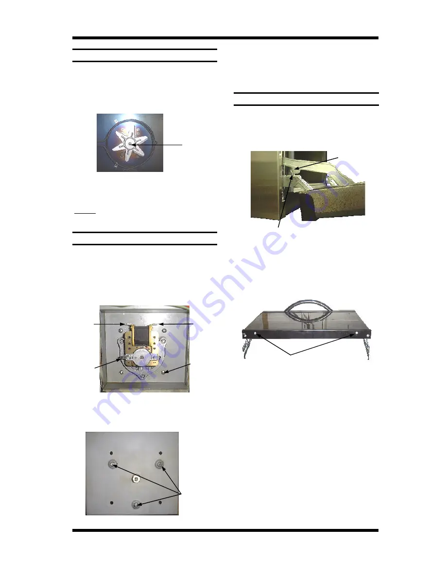
Centre Nut
6.3.12 OUTER GLASS
6.3.11 MOTOR
6.3.10 FAN
1) With baffle removed (refer 6.2.3) undo the
centre nut.
NOTE: LH thread - Turn clockwise to
loosen. Take care not to lose the two
washers.
1) Remove fan (refer 6.3.10), remove service
panel (refer 6.2.2) and then remove the
wires that go to the motor.
2) Undo the four screws holding the motor
bracket in place (from the outside) and
remove motor assembly.
1) Open the oven door.
2) Lock hinges into position by rotating the
hinge locking clip over the hinge locking
notch.
2) Replace and re-assemble in reverse
order.
NOTE:
Reassemble with one washer behind
fan, and one washer in front.
3) Lift door away from the oven and place on
a flat surface.
4) Undo two screws and remove the trim
from the bottom of the door. Carefully
withdraw the glass.
Figure 6.3.11
Figure 6.3.12
Screws (4)
3) Remove three screws holding motor to
bracket and remove motor.
4) Replace and re-assemble in reverse order.
5) Ensure wire connections are correct (fig
6.3.12)
Figure 6.3.13
5) To replace, ensure that the two silicone
rubber seals are in place on the left hand
and right hand side of the door frame.
Clean the inside of the glass and refit it,
ensuring that the silicone rubber seals
cover the outer edges of the glass. Refit
the bottom trim, and fit the door to the
oven.
Figure 6.3.15
Two Screws
Phase
Terminal
Earth /
Ground
Neutral
Hinge Locking Clip
Hinge Locking
Notch
Figure 6.3.14
Summary of Contents for E25
Page 1: ... 1 Revision 3 F3542 SERVICE MANUAL E25 CONVECTION OVEN ...
Page 30: ... 30 Revision 3 F3542 7 ELECTRICAL CIRCUIT SCHEMATIC 7 1 E25 ...
Page 31: ... 31 Revision 3 F3542 7 2 E25B ...
Page 32: ... 32 Revision 3 F3542 8 ELECTRICAL WIRING DIAGRAM 8 1 E25 ...
Page 33: ... 33 Revision 3 F3542 8 2 E25B ...
Page 36: ... 36 Revision 3 F3542 11 PARTS DIAGRAMS 11 1 MAIN ASSEMBLY E25 ...
Page 38: ... 38 Revision 3 F3542 11 2 MAIN ASSEMBLY E25B 110V ONLY ...
Page 46: ... 46 Revision 3 F3542 ...


