20
Gas Conversion and Specifications
Conversion Procedure
NOTE:
•
These conversions should only be carried out by qualified persons. All connections must
be checked for leaks before re-commissioning the appliance.
•
Adjustment of components that have adjustments/settings sealed (e.g. paint sealed) can
only be adjusted in accordance with the following instructions and shell be re-sealed be-
fore re-commissioning this appliance.
•
For all relevant gas specifications refer to the ‘Gas Specifications’ table at the end of this
section.
Main Burners
1.
Turn off the gas supply at the mains supply.
2.
Remove the gas control knobs from the front control panel.
The control knobs are a push fit onto the shaft of the gas
control valves.
3.
Remove the front control panel by slackening the 2 screws
on the underside of the control panel and remove the panel
from the front of the appliance. Take care to
disconnect the electrical connection lead from the rear of
the piezo igniter fitted to the control panel.
4.
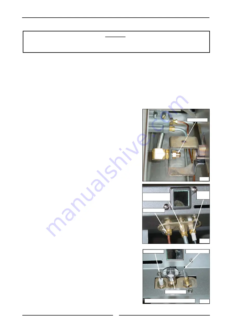
Unscrew and remove the injector (13 mm or ½” A/F) from
the main burner end clamp.
5.
Determine the correct injector size for the corresponding
gas from the rating plate affixed behind the front control
panel and on the inner face of the right hand panel.
6.
Replace with the correct size injectors. Refer to ‘Gas
Specifications Table’ for injector sizes.
Pilot Burners
1.
To remove the pilot burner injector, disconnect the lead to
the piezo igniter and unscrew the piezo igniter from the
mounting bracket (this is precautionary to prevent damage
to the igniter).
2.
Slacken the gas supply tube at the gas control unit end of
the supply tube to allow the tube to be moved easily
without bending.
3.
Disconnect the gas supply tube from the base of the pilot
burner and withdraw the pilot injector from inside the pilot
burner.
4.
Determine the correct injector size for the corresponding gas
from the rating plate affixed to the bulkhead by the manifold
test point.
5.
Re-connect the supply tube to the base of the pilot burner
and tighten the gas supply tube at the gas control unit end.
6.
Refit the piezo igniter to the mounting bracket.
7.
Reconnect the electrical connection to the piezo igniter. This
is a push fit connection.
C
AUTION
:
Ensure that the appliance is isolated from the gas supply before commencing
servicing.
Main Injector
Fig 6
Fig 7
Piezo
Igniter
Pilot Injector Gas
Supply Pipe
Thermocouple
Thermocouple
Pilot Injector
Fig 8
Piezo Igniter
Viewed from Inside the Burner Box
gpd.sunwayinfo.com.cn
gpd.sunwayinfo.com.cn
gpd.sunwayinfo.com.cn


