-33-
Revision 5/F3534
©
Moffat Ltd, April 2005
Turbofan Convection Oven
Bottom Element
Two Screws
Top Element
One Screw
Centre Nut
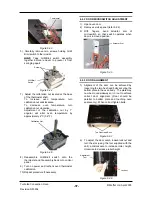
6.3.18 MOTOR
6.3.17 FAN
6.3.16 ELEMENTS
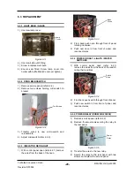
6.3.15 SPRAY NOZZLE (US/CAN ONLY)
1) Inside the oven remove the LH side rack and
baffle (refer 6.2.3), then unscrew the water
injection nozzle.
1) With service panel and baffle removed (refer
6.2.2 and 6.2.3) remove the wires from the
element(s).
2) Unscrew the element from inside the oven.
1) With service panel and baffle removed (refer
6.2.2 and 6.2.3) undo the centre nut.
NOTE: LH thread - Turn clockwise to loosen.
1) Remove fan (refer 6.3.17) and then remove
the wires that go to the motor.
2) Undo the four screws holding the motor
bracket in place (from the outside) and
remove motor assembly.
Figure 6.3.22
Water Injection
Nozzle
2) Clean or replace as required, ensuring debris
free on re-assembly.
2) Replace and re-assemble in reverse order.
Figure 6.3.24
Figure 6.3.23
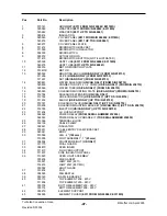
208 V
Top Inner Element
24.5 ohms
Top Outer Element
55.3 ohms
Bottom Element
22.5 ohms
220 - 240V
Top Inner Element
29.5 ohms
Top Outer Element
66.5 ohms
Bottom Element
27.3 ohms
Element Ratings ±5%
3) Pull element carefully to remove.
4) Replace and re-assemble in reverse order.
Figure 6.3.25
Screws (4)
3) Remove three screws holding motor to
bracket and remove motor.
4) Replace and re-assemble in reverse order.
5) Ensure wire connections are correct to the
voltage supply—60 Hz / 50 Hz (fig 6.3.23)
Figure 6.3.26
Three Screws
60 Hz
Terminal
50 Hz
Terminal
Earth /
Ground
Neutral


