background image

-4- 

Revision 5/F3534 

© 

Moffat Ltd, April 2005 

Turbofan Convection Oven 

12. SERVICE 

CONTACTS ................................................................................................................... 54 


APPENDIX A.  POWER RELAY UPGRADE KIT.................................................................................... 56 

Summary of Contents for turbofan E311

Page 1: ... 1 Revision 5 F3534 Moffat Ltd April 2005 Turbofan Convection Oven SERVICE MANUAL E311 E311MS CONVECTION OVEN ...

Page 2: ... 2 Revision 5 F3534 Moffat Ltd April 2005 Turbofan Convection Oven WARNING ALL INSTALLATION AND SERVICE REPAIR WORK MUST BE CARRIED OUT BY QUALIFIED PERSONS ONLY ...

Page 3: ... result IMPORTANT MAKING ALTERATIONS MAY VOID WARRANTIES AND APPROVALS SECTION PAGE NO 1 SPECIFICATIONS 5 2 INSTALLATION 10 3 OPERATION 12 3 1 Description of Controls Not US Can Models 3 2 Description of Controls US Can Models Only 3 3 Explanation of Control System 4 MAINTENANCE 16 4 1 Cleaning 4 2 Routine Procedures 5 TROUBLE SHOOTING GUIDE 18 6 SERVICE PROCEDURES 21 6 1 Fault Diagnosis 6 2 Acces...

Page 4: ... 4 Revision 5 F3534 Moffat Ltd April 2005 Turbofan Convection Oven 12 SERVICE CONTACTS 54 APPENDIX A POWER RELAY UPGRADE KIT 56 ...

Page 5: ...Moffat Ltd April 2005 Turbofan Convection Oven 1 E 45 600 ELECTRICAL ENTRY 580 E 1 120 796 E 1 1 SPECIFICATIONS MODEL E311 NOT US CAN LEGEND Electrical connection entry point FRONT PLAN SIDE Dimensions shown in millimetres ...

Page 6: ...Turbofan Convection Oven ELECTRICAL ENTRY 5 8 13 4 WATER ENTRY 235 8 22 7 8 313 8 15 8 43 4 MODEL E311 US CAN ONLY LEGEND Electrical connection entry point Water entry 9mm 3 8 I D male hose connection FRONT PLAN SIDE Dimensions shown in inches ...

Page 7: ...l 2005 Turbofan Convection Oven 1 120 796 1 E 45 600 ELECTRICAL ENTRY 580 E E 1 MODEL E311MS NOT US CAN LEGEND Electrical connection entry point Water entry 9mm 3 8 I D male hose connection FRONT PLAN SIDE Dimensions shown in millimetres ...

Page 8: ...urbofan Convection Oven 5 8 13 4 WATER ENTRY 235 8 ELECTRICAL ENTRY 22 7 8 313 8 15 8 43 4 MODEL E311MS US CAN ONLY LEGEND Electrical connection entry point Water entry 9mm 3 8 I D male hose connection FRONT PLAN SIDE Dimensions shown in inches ...

Page 9: ...h 370 mm 14 1 2 ELECTRICAL SUPPLY SPECIFICATION OPTIONS 208 V AC 60 Hz 14 6 A 3 2kW 208 V 220 240 V AC 60 Hz 13 0 A 3 1kW 240 V 208 220 V AC 50 Hz 14 6 A 3 2kW 220 V 230 240 V AC 50 Hz 13 0 A 3 1kW 240 V ELECTRICAL PLUG SPECIFICATION REQUIREMENTS Australia 3 pin 250V 15A AS NZ 3112 Canada 3 pin 250V 15A NEMA 6 15 New Zealand 3 pin 250V 15A AS NZ 3112 United Kingdom 3 pin 250V 13A fused BS 1363A Un...

Page 10: ...o be adhered to Top 200mm 8 Rear 25mm 1 Left hand side 25mm 1 Right hand side 25mm 1 2 INSTALLATION IMPORTANT THE OVEN VENT LOCATED ON THE CABINET TOP MUST NEVER BE OBSTRUCTED WARNING THIS APPLIANCE MUST BE GROUNDED DOUBLE STACKING UNITS When it is desired to mount one unit on top of another the 31mm 1 high spacer feet must be used These short feet should be screwed on and the unit lifted on top o...

Page 11: ...tem 3 from the handle item 1 4 Install the handle bracket through the slot on the door side 5 Screw in the two screws item 2 fully then fully screw in the previous two screws item 3 Ensure that they are tight Figure 2 2 Figure 2 3 RATING PLATE LOCATION The rating plate for the E311 convection oven is located at the bottom left corner of the RH side panel Rating Plate ...

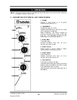
Page 12: ...nts are on 3 BAKE TIMER 1 Hour bake timer Indicator illuminates when time up 0 is reached and buzzer sounds 4 ROAST N HOLD Depress switch to activate ROAST N HOLD function Switch illuminates when ON 5 ROAST TIMER 3 Hour roast timer Indicator illuminates when time up 0 is reached and product held at 75 C 6 LIGHT SWITCH Push switch to activate oven light Light illuminates while button latched in the...

Page 13: ... 1 Hour bake timer Indicator illuminates when time up 0 is reached and buzzer sounds 4 ROAST N HOLD Depress switch to activate ROAST N HOLD function Switch illuminates when ON 5 ROAST TIMER 3 Hour roast timer Indicator illuminates when time up 0 is reached and product held at 167 F 6 STEAM SWITCH Push switch to activate water injection Water injects into oven while the button is depressed 7 LIGHT ...

Page 14: ...ttom of the left hand side rack in the oven Releasing the steam button will close the solenoid valve This feature is used to instantaneously add moisture into the oven cavity or to introduce a reservoir of water in the water trough to maintain humidity in the oven chamber and minimise product s moisture loss during cooking For units manufactured from serial number 232054 power to the temperature c...

Page 15: ...ture If the main thermostat is turned On power will also be supplied to the top outer element coil through the first switch contact of the thermostat front switch assembly In this case the thermostat heating light will also cycle On Off as the Hold thermostat maintains temperature In the Roast and Hold mode the 3 hour timer can be set to a selected roasting time During this time period the normall...

Page 16: ...ack to oven wall swing rack towards centre of oven to disengage location pin at front of side and pull rack forward to remove To replace engage rack in rear holes swing towards side of oven to engage in front hole and replace thumbscrew FAN BAFFLE To remove unscrew the oven lamp glass and lift the baffle out To replace locate the bottom edge of the baffle over the bottom element terminal plate and...

Page 17: ...or deterioration 12 months DOOR PIVOT BUSHES Check for wear 12 months DOOR CATCH Ensure that catch is adjusted such that the door closes properly 12 months ELEMENTS Check that element resistances are correct to their rating refer 6 3 13 12 months WATER NOZZLE US CAN ONLY Check for liming scale build up in water nozzle 12 months ...

Page 18: ...t diagnosis 6 1 2 Wiring Close door Adjust Refer service section 6 4 2 Replace Refer service section 6 3 2 Replace Refer service section 6 3 18 Check and tighten any loose wiring OVEN LIGHT NOT ILLUMINATING DOOR OPEN OVEN LIGHT NOT ILLUMINATING DOOR CLOSED Blown bulb No power to light Refer fault diagnosis 6 1 3 Blown bulb Light switch faulty Refer fault diagnosis 6 1 4 Replace Refer service secti...

Page 19: ...ways rotate past 20 minutes then back to desired time Refer service section 6 4 5 Replace Refer service section 6 3 6 Replace Refer service section 6 3 7 Replace Refer service section 6 3 3 NO HEAT Power relay faulty From S N 232054 only Refer fault diagnosis 6 1 9 Hold relay mini contactor faulty Refer fault diagnosis 6 1 9 Thermostat faulty Refer fault diagnosis 6 1 9 Replace Refer service secti...

Page 20: ...fer fault diagnosis 6 1 18 Hold thermostat set temperature incorrect Hold thermostat faulty Refer fault diagnosis 6 1 19 Depress switch Switch will illuminate Correct electrical fault replace timer Refer service section 6 3 8 Replace Refer service section 6 3 4 Replace Refer service section 6 3 3 Replace Refer service section 6 3 8 Adjust to correct temperature Refer service section 6 4 4 Replace ...

Page 21: ...Grill Indicator Not Working 26 6 1 17 Roast Timer 180 Minute Will Not Time Down 26 6 1 18 No Hold Indicator 27 6 1 19 Holding Temperature Incorrect 27 6 2 ACCESS 28 6 2 1 Control Panel 28 6 2 2 Service Panel Rear Panel 28 6 2 3 Baffle 28 6 2 4 Control Panel Rear 28 6 3 REPLACEMENT 29 6 3 1 Light Bulb Glass 29 6 3 2 Door Microswitch 29 6 3 3 Indicator Neon Light 29 6 3 4 Power Roast Lights Water Sw...

Page 22: ...l E311 34 6 3 22 Door Seals 35 6 3 23 Door Pivot Bushes 35 6 3 24 Outer Glass E311MS 35 6 3 25 Inner Glass E311MS 35 6 3 26 Outer Glass Seal E311MS 35 6 3 27 Inner Glass Seal E311MS 36 6 4 ADJUSTMENT CALIBRATION 36 6 4 1 Thermostat Calibration 36 6 4 2 Door Microswitch Adjustment 37 6 4 3 Door Alignment 37 6 4 4 Hold Temperature Adjustment 38 6 4 5 60 Minute Timer Zero Position Adjustment 38 ...

Page 23: ...ck the supply voltage across lamp housing terminals at rear of oven If the voltage is correct replace the bulb if faulty If the bulb is OK check lamp housing Replace if faulty If there is no voltage open oven door and manually depress door microswitch actuator at top right of oven If this activates the fan then the microswitch actuator arm at rear of oven requires adjustment Check voltage across m...

Page 24: ...timer If there is no voltage at terminal 1 then check wiring 6 1 9 NO HEAT Power relay faulty From S N 232054 Check voltage to terminal 7 on power relay on rear panel of oven If there is no voltage then check wiring to the relay 6 1 8 60 MINUTE TIMER NO TIME UP INDICATOR Indicator faulty With the timer in the zero position check for voltage across the indicator light If correct then the indicator ...

Page 25: ... outside these ranges then the thermostat requires recalibration NOTE Thermostat cycling span should be 15 C or 27 F 6 1 12 BOTTOM ELEMENT NOT WORKING Element faulty blown With the thermostat on and heating check voltage across bottom element terminals at rear of oven If the voltage is correct then check the current draw of element If there is no current draw then element is faulty replace Figure ...

Page 26: ...ator is faulty replace If there is no voltage then check wiring 6 1 16 GRILL INDICATOR NOT WORKING No power to timer Check the voltage at terminal 5 on underside of the 180 minute timer Check that one lead of timer motor is connected to terminal 5 of timer and the other lead is connected to neutral of Roast n Hold switch If voltage at terminal 5 is correct and wiring is correct then the timer moto...

Page 27: ...ting Test the voltage across the bottom element and top element terminals at the rear of oven If the voltage is correct then refer Fault Bottom element not working trouble shooting section NOTE If the main thermostat is set to off vertical position and Roast n Hold mode is selected then only the bottom element will heat If there is no voltage at the element terminals check the voltage at terminal ...

Page 28: ...FFLE 3 Panel is now free to hinge along right hand side When closing the panel ensure wires and capillary tube are clear of metal or other terminals Figure 6 2 1 Microswitch Button Two Screws 2 Remove panel Figure 6 2 2 Figure 6 2 3 3 Remove baffle Figure 6 2 4 6 2 4 CONTROL PANEL REAR Buzzer Power Switch Heating Indicator Grill Broil Indicator Thermostat Bake Time Up Indicator Roast n Hold Switch...

Page 29: ...nsure seal fitted Screw lamp cover into holder with baffle fitted do not over tighten Lamp Cover Figure 6 3 1 3 Transfer wires to new micro switch and re assemble 4 Adjust microswitch refer 6 4 2 Figure 6 3 2 2 From back push neon through front of panel rotating clockwise 3 Push new neon in from front of panel and reconnect wires 2 From back push switch through front of panel 3 Push new switch in ...

Page 30: ...3 8 ROAST TIMER 1 Remove roast timer knob by pulling it firmly away from control panel 2 Open control panel refer 6 2 1 and undo two screws securing timer 6 3 9 THERMOSTAT 1 Pull knob off front of thermostat 2 Open control panel refer 6 2 1 and undo two screws securing thermostat 3 Transfer wires to new timer 4 Withdraw old timer and insert new timer securing with screws 5 Replace knob 3 Transfer ...

Page 31: ...TOR TO S N 232053 1 Open control panel refer 6 2 1 and transfer wires from old mini contactor to new contactor 2 Remove two screws securing old mini contactor to control panel Figure 6 3 16 3 Secure new mini contactor to control panel using two screws Two Screws 6 3 11 HOLD RELAY FROM S N 232054 1 Open control panel refer 6 2 1 and transfer wires from old hold relay to new relay 2 Remove two screw...

Page 32: ...h screws and re assemble Check that flow direction as marked on valve is correct flow into spray nozzle Brass Connections Two Screws 6 3 14 WATER SOLENOID CLEANING US CAN ONLY 1 Remove water solenoid refer 6 3 13 2 Remove the two screws securing the bracket to the solenoid Two Screws 3 Remove the valve assembly Figure 6 3 20 4 Clean the valve assembly removing all dirt and grime from the valve sea...

Page 33: ... 2 Undo the four screws holding the motor bracket in place from the outside and remove motor assembly Figure 6 3 22 Water Injection Nozzle 2 Clean or replace as required ensuring debris free on re assembly 2 Replace and re assemble in reverse order Figure 6 3 24 Figure 6 3 23 208 V Top Inner Element 24 5 ohms Top Outer Element 55 3 ohms Bottom Element 22 5 ohms 220 240V Top Inner Element 29 5 ohms...

Page 34: ...retaining lugs over to hold the glass in place Refit outer glass as above Retaining Lugs Figure 6 3 31 4 Remove screws securing door handle Figure 6 3 28 Figure 6 3 27 LH Screw 5 Remove two screws in top trim and two screws in bottom trim of door and remove trim panels Screws Figure 6 3 29 6 Lift outer glass away from door 7 To replace ensure that the two silicone rubber seals are in place on the ...

Page 35: ...m screws 4 Figure 6 3 33 3 Place door on bench with door outer facing up Lift door outer up removing it from door assembly Remove outer glass 4 To replace clean inner and outer glass ensure the silicone rubber seal has not been displaced and refit door outer Reassemble in reverse order 5 Reinstall door by reversing steps one to three of section 6 3 19 6 3 25 INNER GLASS E311MS Door Glass Door Oute...

Page 36: ...RE CARRYING OUT ANY ADJUSTMENT 1 Turn off power 2 Remove thermostat knob by pulling it firmly away from control panel 3 Open control panel refer 6 2 1 Remove two screws on control panel holding thermostat 4 The thermostat can now be removed Figure 6 4 2 Screws Calibration Nut Thermostat Figure 6 4 1 6 4 1 THERMOSTAT CALIBRATION 6 4 ADJUSTMENT CALIBRATION 6 3 27 INNER GLASS SEAL E311MS 1 Remove the...

Page 37: ...at procedure if necessary Screws Grill Broil Switch Figure 6 4 4 Calibration Nut Figure 6 4 3 Thermostat 6 4 3 DOOR ALIGNMENT 6 4 2 DOOR MICROSWITCH ADJUSTMENT 1 Open oven door 2 Remove service panel refer 6 2 2 3 With fingers bend actuator arm of microswitch so that switch operates when door is in closed position 1 Alignment of the door can be achieved by loosening the two hex head bolts securing...

Page 38: ...ure This dial is located inside the control panel Hold Thermostat Dial Figure 6 4 9 6 4 5 60 MINUTE TIMER ZERO POSITION ADJUSTMENT 1 Remove 60 minute timer knob by pulling it firmly away from control panel 2 Open control panel refer 6 2 1 Loosen two screws on control panel holding 60 minute timer Two Screws Figure 6 4 10 3 The timer can now be rotated as required to ensure that the buzzer sounds a...

Page 39: ...ELAY 3 4 6 9 1 7 B A HOLD SWITCH WATER SWITCH OPTION ONLY WATER SOLENOID OPTION ONLY HOLD RELAY NO E L2 N TIME UP B BUZZER 2 1 3 5 4 6 L1 TIMER SWITCH POWER 3 4 1Hr Ø 1 2 1 60Hz 3 T STAT HOLD HOLD LIGHT OVEN HEATING 50Hz FAN 4 SWITCH MICRO NO NC DOOR OVEN OUTER TOP T STAT 2 INNER TOP GRILL 5 6 TIMER 3Hr 1 P5 P6 6 5 M 2 3 1 4 From Serial Number 232054 ...

Page 40: ... 40 Revision 5 F3534 Moffat Ltd April 2005 Turbofan Convection Oven To Serial Number 232053 ...

Page 41: ... 17 3 1 3 4 17 14 12 13 3 6 2 1 5 4 32 28 33 HEAT 31 21 GRILL 44 ELEMENT TOP 38 45 37 39 23 22 20 9 P E N MICROSWITCH COM NO NC 9 8 6 FAN MOTOR 3 60Hz 50Hz 10 4 E 40 47 40 1 47 WATER T STAT HOLD 18 19 8 LIGHTS 6 2 1 2 1 5 43 46 7 48 36 45 41 ELEMENT BOTTOM 36 MAINS TERMINAL BLOCK 44 29 1 37 42 E N Ø 48 7 SOLENOID WATER 20 19 3 1 6 4 9 7 B A 52 51 50 51 53 53 POWER RELAY 11 50 15 35 13 14 B 9 A 7 6...

Page 42: ... 42 Revision 5 F3534 Moffat Ltd April 2005 Turbofan Convection Oven Dotted lines indicate wiring used only on models with water injection To Serial Number 232053 ...

Page 43: ...S N 232053 018223 Hold Thermostat 002990 Microswitch 003002 Oven Lamp Glass 003434 Silk Gasket 013521 Oven Lamp 40W Miniature Edison Screw E311 014218 Oven Lamp 25W Miniature Edison Screw E311MS MOTOR ELEMENTS 003113 Oven Top Element 208 Volts 003114 Oven Bottom Element 208 Volts 011604 Oven Top Element 240 Volts 003074 Oven Bottom Element 240 Volts 013431K Fan Motor 013432 Oven Fan STEAM SYSTEM O...

Page 44: ... 44 Revision 5 F3534 Moffat Ltd April 2005 Turbofan Convection Oven RACKS 023255 Oven Side Rack LH 023256 Oven Side Rack RH 023254 Oven Rack 004874 Bottom Element Guard 004595 Fan Baffle ...

Page 45: ...on 5 F3534 Moffat Ltd April 2005 Turbofan Convection Oven 10 ACCESSORIES OVEN RACKS PART NO 23254 100 MM FOUR INCH FOOT OPTION PART NO 13048 A25 A311 STAINLESS STEEL STAND 25 MM ONE INCH FOOT OPTION PART NO 13908 ...

Page 46: ... 46 Revision 5 F3534 Moffat Ltd April 2005 Turbofan Convection Oven 11 PARTS DIAGRAMS 11 1 MAIN ASSEMBLY ...

Page 47: ...UNTING PLATE US CAN ONLY FROM S N 258733 17 012784 SOLENOID EXTENSION US CAN ONLY 18 012782 HOSE CONNECTOR US CAN ONLY UP TO S N 258732 19 011634 ELBOW US CAN ONLY UP TO S N 258732 20 012781 SOLENOID VALVE US CAN ONLY UP TO S N 258732 21 019208 SOLENOID MOUNTING BRACKET US CAN ONLY UP TO S N 258732 22 012785 INJECTOR US CAN ONLY UP TO S N 258732 23 011404 L H OVEN SUPPORT 24 024562 POWER RELAY FRO...

Page 48: ...L SEAL 455mm 50 023257 OVEN SEAL ASSEMBLY HORIZONTAL 023278 HORIZONTAL SEAL 584mm 51 004877 PIVOT COVER BLACK E311 ONLY 004994 PIVOT COVER ST ST E311MS ONLY 52 023243 PIVOT SUPPORT TOP ASSEMBLY 53 DOOR ASSEMBLY REFER SECTION 11 3 11 4 54 CONTROL ASSEMBLY SEE SECTION 11 2 55 025502 DOOR BUSH E311 FROM S N 260862 E311MS ALSO USED ON CONTROL PANEL PIVOT 013610 DOOR BUSH E311 UP TO S N 260861 ALSO USE...

Page 49: ...TAT 3 021538 HOLD THERMOSTAT BRACKET AFFIX 018209 LABEL 4 017121 THERMOSTAT 50 300 ºC 5 011760 TIMER 1 Hr 6 011419 TIMER 3 Hr 240V 50 Hz 011983 TIMER 3 Hr 240V 60 Hz 7 024562 HOLD RELAY FROM SERIAL NUMBER 232054 022281 HOLD MINI CONTACTOR TO SERIAL NUMBER 232053 8 021536 RELAY CONTACTOR BRACKET 9 018789 BALL CATCH PLATE 10 011005 BALL CATCH LOCKNUT 11 021442 TIMER MOUNTING PANEL 12 011794 BUZZER ...

Page 50: ... 013610 DOOR BUSH 16 024773 LIGHT SWITCH LATCHING USA CAN ONLY FROM S N 258733 021474 LIGHT SWITCH MOMENTARY USA CAN ONLY UP TO S N 258732 17 024773 LIGHT SWITCH LATCHING NOT USA CAN FROM S N 260862 021474 LIGHT SWITCH MOMENTARY NOT USA CAN UP TO S N 260861 021474 STEAM SWITCH USA CAN ONLY 18 020823 THERMOSTAT TIMER KNOBS 19 020849 INDICATOR LIGHT 20 021476 ROAST N HOLD SWITCH 21 021473 POWER SWIT...

Page 51: ...MOSTAT KNOB 10 018209 HOLD THERMOSTAT LABEL 11 011419 THREE HOUR TIMER 50Hz 011983 THREE HOUR TIMER 60Hz 12 021442 TIMER MOUNTING PANEL 13 021538 HOLD THERMOSTAT BRACKET 14 018223 HOLD THERMOSTAT 15 025544 CONTROL PANEL WA BAKBAR BLUE SEAL 025503 CONTROL PANEL WA MOFFAT 16 025531 CONTROL PANEL OVERLAY BAKBAR C 025532 CONTROL PANEL OVERLAY BLUE SEAL C 025530 CONTROL PANEL OVERLAY MOFFAT F 17 021473...

Page 52: ... UP TO S N ALSO USED ON CONTROL PANEL PIVOT 2 023615 TOP TRIM 3 023616 BOTTOM TRIM 4 004992 DOOR INNER FROM S N 004875 DOOR INNER UP TO S N 5 021465 HANDLE BRACKET HANDLE ASSEMBLY 021469 6 021468 HANDLE HANDLE ASSEMBLY 021469 7 090200 SILICON EXTRUSION 1 90M 8 023263 DOOR INNER GLASS 9 004876 DOOR GLASS CLAMP ANGLE 10 090225 SILICON EXTRUSION 0 96M 11 023264 DOOR OUTER GLASS 1 3 1 2 4 5 6 8 9 10 1...

Page 53: ...004992 DOOR INNER 2 023263 DOOR GLASS 3 025498 GLASS CLAMP ANGLE 4 090200 INNER GLASS SEAL EXTRUSION 5 090201 OUTER GLASS SEAL EXTRUSION 6 090415 INSULATION 38mm 7 025504 DOOR OUTER PANEL WA 8 025502 PIVOT BUSH 9 025501 DOOR CATCH PLATE 10 025499 DOOR HANDLE 11 4 ST ST DOOR ASSEMBLY E311MS only ...

Page 54: ...MOFFAT PTY 28 Greenhill Rd Tel 08 8274 2116 Wayville SA 5034 Spare Parts Free Call 1800 337 963 WESTERN AUSTRALIA MOFFAT PTY PO Box 689 Tel 08 9305 8855 Joondalup Business Centre WA 6027 Spare Parts Free Call 1800 337 963 NATIONAL COVERAGE FOR 24 HOUR SERVICE OR MAINTENANCE DIAL FREE CALL 1800 622 216 AUSTRALIA ONLY CANADA Lessard Agencies Limited Tel 416 766 2764 PO Box 97 Fax 416 760 0394 Stn D ...

Page 55: ... 7 Mount St Business Park Tel 0121 327 5575 Mount Street Fax 0121 327 9711 Nechells Birmingham B7 5QU England UNITED STATES OF AMERICA MOFFAT INC 3765 Champion Blvd Winston Salem Tel 1 800 551 8795 NC27115 Fax 336 661 9546 NATIONAL COVERAGE FOR SERVICE OR MAINTENANCE DIAL FREE CALL 1800 551 8795 USA ONLY ...

Page 56: ...e to vacant phase L1 terminal on terminal block and to terminal 7 on relay 6 Connect long thick red wire 950mm to power relay terminal 4 and remaining long thin wire 1050mm to relay terminal A Feed these wires through the plastic bush in the rear of the oven and into the control cavity 7 Loosen screws and open the control panel 8 Remove and discard wire from terminal 2 on the power switch to termi...

Page 57: ... 57 Revision 5 F3534 Moffat Ltd April 2005 Turbofan Convection Oven Circuit schematic new wires shown in bold Figure 3 ...

Reviews: