background image

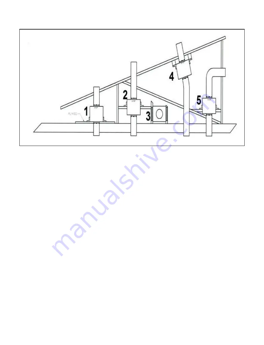
INSTALLATION - POSITIONS


WARNING 


1. Use ¾” plywood to mount and separate from ceiling joists bed. 


2. Install additional support cross members to truss for a suspended mount. 


3. Install additional support cross members to truss for horizontal mounting. 


4. Install additional blocking to mount under the roof rafter. 


5. Install additional cross members to ceiling joists with a 90 degree elbow to exit side. 


Important Notes: 


Adding plywood to each installation may simplify install. 


10” diameter ducting is recommended for optimal performance of this product.  8” diameter may be used 
if ducting space is limited but this may reduce the unit’s performance. 


Summary of Contents for Proline BSPL024V2

Page 1: ...SUMER IS TO RE TAIN THEM FOR FUTURE REFERENCE 4 PLEASE OBSERVE ALL LOCAL AND NATIONAL BUILDING CODES AND ORDINANCES IF NO LO CAL CODES ARE APPLICABLE PLEASE FOLLOW ALL WIRING REQUIREMENTS IN ACCORDANCE WITH THE NATIONAL ELECTRICAL CODE ANSI NFPA 70 EDITION 5 PLEASE CHECK WITH A QUALIFIED AND TRAINED INSTALLER OR YOUR LOCAL CODES FOR ANY MAKE UP AIR REQUIREMENTS 6 THIS HOOD IS FOR RESIDENTIAL USE O...

Page 2: ...4 Blower Installation 15 Custom Duct Installation 16 Installation of Pyramid Style Dimensions 17 Site Preparation 18 The Correct Height 19 Duct Information 20 Blower Installation 21 Flue Installation 22 Installation of Low Profile Series Dimensions 23 Site Preparation 24 The Correct Height 25 Duct Information and Wiring 26 Installation of Low Profile Re Circulating Series Dimensions 27 Site Prepar...

Page 3: ...R SERVICING UNIT SWITCH POWER OFF TO THE UNIT AT THE SERVICE PANEL AND LOCK OUT THE SER VICE PANEL IF THE SERVICE PANEL CAN NOT BE LOCKED OUT PLEASE AFIX A WARNING DEVICE PROMINENTLY SUCH AS A TAG TO THE SERVICE PANEL WARNING WARNING P N 750306 Page 3 TO REDUCE RISK OF FIRE ELECTRIC SHOCK OR INJURY TO PERSONS OBSERVE THE FOLLOW ING INSTALLATION WORK AND ELECTRICAL WORK MUST BE PERFORMED BY QUALIFI...

Page 4: ...N TURN OFF THE BURNER TAKE CARE TO AVOID AND PREVENT BURNS IF FLAMES DO NOT EX TINGUISH EVACUATE THE PREMISES AND CALL THE FIRE DEPARTMENT NEVER HANDLE OR PICK UP A FLAMING PAN DO NOT USE WATER INCLUDING WET DISHCLOTHS OR TOWELS A VIOLENT STEAM EXPLO SION MAY ENSUE DO NOT TURN ON HOOD TO EVACUATE SMOKE TURN OFF HOOD USE AN EXTINGUISHER ONLY IF YOU HAVE A CLASS ABC EXTINGUISHER AND YOU CAN OPERATE ...

Page 5: ...pectations We establish and maintain an environment that encourages all employees to pursue continuous improvement in qual ity and productivity Our quality policy is monitored by the highest levels of management We hope you enjoy your new appliance and we THANK YOU again for believing in our product as much as we do The staff and team at Prizer Stove Works LOW PROFILE HOOD RECIRCULATING LOW PROFIL...

Page 6: ...ke no other appliance can What s more this high quality high performance appliance is backed by our professional service network from coast to coast to provide you with quick competent technical service should the need arise Please take a few moments now to fill in the information below for your future reference In the event you require parts or service this information will be needed to ensure WE...

Page 7: ... NOT UPRIGHT MAJOR DAM AGE CAN OCCUR TO YOUR APPLIANCE IF DAMAGE IS DISCOVERED DO NOT REFUSE DELIVERY CONTACT THE DEALER AND FILE APPROPRIATE FREIGHT CLAIMS SAVE ALL PACKAGING MATERIAL DO NOT CONTACT THE MANUFACTURER YOUR APPLI ANCE WAS SHIPPED FROM THE DEALER YOU PURCHASED IT FROM SHIPPING DAMAGE CLAIMS ARE TO BE RESOLVED BETWEEN THE CUSTOMER SHIPPING CARRIER AND DEALER THE MANUFACTURER MAY ASSIS...

Page 8: ... Baffle Filters Two 2 Pre Installed Lights Lid for Electrical Box Use and Care Manual with Wiring Diagram PL48240 PL54240 24 Depth No blower Sold and Packaged Separately Six 6 Stainless Steel Baffle Filters Three 3 Pre Installed Lights Lid for Electrical Box Use and Care Manual with Wiring Diagram PL60240 PL66240 24 Depth No blower Sold and Packaged Separately Six 6 Stainless Steel Baffle Filters ...

Page 9: ...Lid for Electrical Box Use and Care Manual with Wiring Diagram Duct cover sold packed in separate box 2 of2 PC48240 PC54240 24 Depth No blower Sold and Packaged Separately Six 6 Stainless Steel Baffle Filters Three 3 Pre Installed Lights Lid for Electrical Box Use and Care Manual with Wiring Diagram Duct cover sold packed in separate box 2 of2 PC60240 PC66240 24 Depth No blower Sold and Packaged S...

Page 10: ...s Lid for Electrical Box Use and Care Manual with Wiring Diagram BS LPLR24240 BS LPLR30240 24 depth One Pre Installed 520 CFM blower Two 2 Stainless Steel Baffle Filters Two 2 Charcoal Filters Two 2 Pre Installed Lights Lid for Electrical Box Use and Care Manual with Wiring Diagram BS LPLR36240 24 depth One Pre Installed 520 CFM blower Four 4 Stainless Steel Baffle Filters Four 4 Charcoal Filters ...

Page 11: ...S LOCATED NEAR THE REAR CENTER OF HOOD 3 3 16 FROM HOOD BOTTOM ELECTRICAL REQUIREMENTS 15 AMPS AT 120 VOLTS LIGHT BULBS ARE HALOGEN G9 120V 25W BULBS ARE OPERATED BY A DIMMER SWITCH BLOWER IS VARIABLE SPEED AND MUST BE PURCHASED SEPERATELY 10 5 10 5 24 5 3 3 16 3 3 16 P N 750306 Page 11 ...

Page 12: ... HOOD ON IT WHILE INSTALLING MARK A CENTER LINE ON THE WALL EQUAL TO THE ENTIRE HEIGHT OF THE HOOD TO ASSIST WITH THE PROPER DUCT ALIGNMENT AND HOOD PLACEMENT DETERMINE STUD LOCATION AND MARK IT CLEARLY BECAUSE OF THE WEIGHT OF THE HOOD MAKE SURE THAT THE MOUNTING SCREWS ARE DRIVEN INTO THE FRAMING AND NOT JUST THE DRYWALL IT MAY BE NECESSARY TO DRILL ADDITIONAL HOLES INTO THE CANOPY FOR PROPER AL...

Page 13: ... MORE THAN 36 ABOVE THE COUNTERTOP THESE DIMENSIONS PROVIDE FOR SAFE AND EFFICIENT OPERATION OF THE HOOD IF FOR SOME REASON THE HOOD IS MOUNTED GREATER THAN 72 FROM THE FLOOR IT MUST BE 6 WIDER THAN THE RANGE ALL PL MODEL HOODS HAVE THE FLEXIBILITY TO EITHER DUCT FROM THE TOP OR REAR CHECK MANUAL FOR RECOMMENDED TRANSITIONS TOP DISCHARGE REAR DISCHARGE HEIGHT FROM FLOOR 68 MIN 72 MAX 167 6cm 182 9...

Page 14: ...OR OPTIMAL PERFORMANCE IMPORTANT PLANNING INFORMATION PROPER INSTALLATION OF DUCTING IS EXTREMELY INPORTANT FOR OPTIMAL PERFORMANCE OF YOUR BLUESTAR VENTILLATION SYSTEM ALL CFM S ARE BASED ON TESTS AT 0 1 STATIC PRESSURE WITHOUT STATIC PRESSURE ALL CFM S WOULD BE OVERSTATED STRAIGHT RUNS OR GRADUAL TURNS ARE BEST NEVER USE FLEXIBLE DUCT WORK PROPER PERFORMANCE IS DEPENDENT ON PROPER DUCT INSTALLAT...

Page 15: ...BS PLIB1200 INTERNAL BLOWER KIT REFER TO WIRING DIAGRAM 1 REMOVE SHIPPING BRACKET FROM HOOD DO NOT DISCARD SCREWS FOR FAN 1 1 INSTALL BLOWER BRACKET WITH THE SCREWS REMOVED FROM THE SHIPPING BRACKET 2 LOCATE THE TERMINAL BLOCK INSIDE THE ELECTRICAL SUPPLY BOX 3 CONNECT FAN 1 WIRE TO TERMINAL BLOCK 4 4 CONNECT FAN 1 WIRE TO TERMINAL BLOCK 6 5 CONNECT THE 115 VOLT SUPPLY WIRE TO TERMINAL BLOCK 2 6 C...

Page 16: ...TTACHMENT HOLES REMOVE POP RIVETS FROM PRO HOOD THAT CORRESPOND WITH THE SMALL HOLES ON THE DUCT COVER INSTALL HOOD TO CORRECT HEIGHT BE CAREFUL TO LEAVE 12 FOR DUCT COVER SLIDE DUCT COVER OVER TOP OF HOOD MAKE SURE SMALL HOLES IN DUCT COVER FLANGE LINE UP WITH HOLES IN HOOD WHERE RIVETS WERE REMOVED FROM INSIDE HOOD ATTACH DUCT COVER TO HOOD USING SHEETMETAL SCREWS P N 750306 Page 16 ...

Page 17: ...DIMENSIONS OF THE PYRAMID STYLE SERIES HOOD P N 750306 Page 17 ...

Page 18: ... THE HOOD ALONG THE LINE SO YOU MAY REST THE HOOD ON IT WHILE INSTALLING MARK A CENTER LINE ON THE WALL EQUAL TO THE ENTIRE HEIGHT OF THE HOOD TO ASSIST WITH THE PROPER DUCT ALIGNMENT AND HOOD PLACEMENT DETERMINE STUD LOCATION AND MARK IT CLEARLY BECAUSE OF THE WEIGHT OF THE HOOD MAKE SURE THAT THE MOUNTING SCREWS ARE DRIVEN INTO THE FRAMING AND NOT JUST THE DRYWALL IT MAY BE NECESSARY TO DRILL AD...

Page 19: ...E COUNTERTOP THESE DIMENSIONS PROVIDE FOR SAFE AND EFFICIENT OPERATION OF THE HOOD IF FOR SOME REASON THE HOOD IS MOUNTED GREATER THAN 72 FROM THE FLOOR IT MUST BE 6 WIDER THAN THE RANGE ALL PC MODELS TOP DUCT ONLY NOTE THE PC HOOD CAN BE DUCTED TO THE REAR WITH THE USE OF A 90 DGREE ELBOW NOT INCLUDED CHECK MANUAL FOR RECOMMENDED TRANSITIONS REAR DISCHARGE TOP DISCHARGE HEIGHT FROM FLOOR 68 MIN 7...

Page 20: ... IS EXTREMELY INPORTANT FOR OPTIMAL PERFORMANCE OF YOUR BLUESTAR VENTILLATION SYSTEM ALL CFM S ARE BASED ON TESTS AT 0 1 STATIC PRESSURE WITHOUT STATICE PRESSURE ALL CFM S WOULD BE OVERSATED STRAIGHT RUNS OR GRADUAL TURNS ARE BEST NEVER USE FLEXIBLE DUCT WORK PROPER PERFORMANCE IS DEPENDENT ON PROPER DUCT INSTALLATION USE A QUALIFIED AND TRAINED INSTALLER CONSULT WITH LOCAL CODES FOR MAKE UP AIR R...

Page 21: ... INSTALLATION OF IBS PCIB1200 INTERNAL BLOWER KIT REFER TO WIRING DIAGRAM 1 REMOVE SHIPPING BRACKET FROM HOOD DO NOT DISCARD SCREWS FOR FAN 1 1 INSTALL BLOWER BRACKET WITH THE SCREWS REMOVED FROM THE SHIPPING BRACKET 2 LOCATE THE TERMINAL BLOCK INSIDE THE ELECTRICAL SUPPLY BOX 3 CONNECT FAN 1 WIRE TO TERMINAL BLOCK 4 4 CONNECT FAN 1 WIRE TO TERMINAL BLOCK 6 5 CONNECT THE 115 VOLT SUPPLY WIRE TO TE...

Page 22: ...D LOWERING POINT BY SUBTRACTING 15 FROM THE TO TAL HEIGHT NEEDED 3 USE THE RETAINING SCREWS TO FASTEN IN PLACE 4 SLIDE THE DUCT COVER IN PLACE AND FASTEN FROM INSIDE CANOPY USING SHEET METAL SCREWS NOTE FOR INSTALLATIONS WITH CEILINGS ABOVE 9 USE OPTIONAL CUSTOM FLUES SEE PRODUCT LITERATURE FOR DETAILS MODEL A DIM B MAXIMUM C DIM BS PC30240 15 27 12 BS PC36240 15 27 12 BS PC42240 15 27 15 BS PC482...

Page 23: ...AL CONNECTION IS LOCATED ON TOP FOR STANDARD TOP EXHAUST AND ON REAR FOR OPTIONAL REAR EXHAUST SEE DETAIL BELOW ELECTRICAL REQUIREMENTS 15 AMPS AT 120 VOLTS LIGHT BULBS ARE HALOGEN G9 120V 25W BULBS ARE OPERATED BY A DIMMER SWITCH BLOWER IS VARIABLE SPEED P N 750306 Page 23 ...

Page 24: ...E HOOD ALONG THE LINE SO YOU MAY REST THE HOOD ON IT WHILE INSTALLING MARK A CENTER LINE ON THE WALL EQUAL TO THE ENTIRE HEIGHT OF THE HOOD TO ASSIST WITH THE PROPER DUCT ALIGNMENT AND HOOD PLACEMENT DETERMINE STUD LOCATION AND MARK IT CLEARLY BECAUSE OF THE WEIGHT OF THE HOOD MAKE SURE THAT THE MOUNTING SCREWS ARE DRIVEN INTO THE FRAMING AND NOT JUST THE DRYWALL IT MAY BE NECESSARY TO DRILL ADDIT...

Page 25: ...OM FLOOR 68 MIN 72 MAX 167 6cm 182 9cm COUNTERTOP HEIGHT ABOVE COUNTERTOP 30 MIN 36 MAX 76 2CM 91 4CM REAR EXHAUST INSTRUCTIONS 1 REMOVE BAFFLE FILTERS IF ALREADY INSTALLED AND SET UNIT DOWN WITH THE BLOWER EXHAUST FACING UPWARD ON A CLEAN NON ABRASIVE BLAN KET 2 REMOVE ALL L BRACKET BLOWER ASSEMBLY MOUNTING SCREWS AND SET THEM ASIDE FOR REAS SEMBLY LATER 3 REMOVE THE L BRACKET BLOWER ASSEMBLY FRO...

Page 26: ...RFORMANCE OF YOUR BLUESTAR VENTILLATION SYSTEM ALL CFM S ARE BASED ON TESTS AT 0 1 STATIC PRESSURE WITHOUT STATIC PRESSURE ALL CFM S WOULD BE OVERSTATED STRAIGHT RUNS OR GRADUAL TURNS ARE BEST NEVER USE FLEXIBLE DUCT WORK PROPER PERFORMANCE IS DEPENDENT ON PROPER DUCT INSTALLATION USE A QUALIFIED AND TRAINED INSTALLER CONSULT WITH LOCAL CODES FOR MAKE UP AIR REQUIREMENTS LOW PROFILE HOOD WIRING P ...

Page 27: ... LOCATION FOR THE ELECTRICAL CONNECTION IS LOCATED ON TOP OR REAR SEE DETAIL BELOW ELECTRICAL REQUIREMENTS 15 AMPS AT 120 VOLTS LIGHT BULBS ARE HALOGEN G9 120V 25W BULBS ARE OPERATED BY A DIMMER SWITCH BLOWER IS VARIABLE SPEED P N 750306 Page 27 ...

Page 28: ...THE HOOD ALONG THE LINE SO YOU MAY REST THE HOOD ON IT WHILE INSTALLING MARK A CENTER LINE ON THE WALL EQUAL TO THE ENTIRE HEIGHT OF THE HOOD TO ASSIST WITH THE PROPER DUCT ALIGNMENT AND HOOD PLACEMENT DETERMINE STUD LOCATION AND MARK IT CLEARLY BECAUSE OF THE WEIGHT OF THE HOOD MAKE SURE THAT THE MOUNTING SCREWS ARE DRIVEN INTO THE FRAMING AND NOT JUST THE DRYWALL IT MAY BE NECESSARY TO DRILL ADD...

Page 29: ...OF THE HOOD SHOULD NEVER BE MORE THAN 72 ABOVE THE FLOOR OR MORE THAN 36 ABOVE THE COUNTERTOP THESE DIMENSIONS PROVIDE FOR SAFE AND EFFICIENT OPERATION OF THE HOOD IF FOR SOME REASON THE HOOD IS MOUNTED GREATER THAN 72 FROM THE FLOOR IT MUST BE 6 WIDER THAN THE RANGE HEIGHT FROM FLOOR 68 MIN 72 MAX 167 6cm 182 9cm COUNTERTOP HEIGHT ABOVE COUNTERTOP 30 MIN 36 MAX 76 2CM 91 4CM RE CIRCULATING HOOD W...

Page 30: ...ER DISASSEMBLY WILL VOID THE WAR RANTY CANOPY DO NOT USE ABRASIVE CLEANERS STEEL WOOL PADS ABRASIVE CLOTHS OR CLEAN ERS WITH CHLORIDES DO NOT ALLOW GREASE TO ACCUMULATE FOR BEST RESULTS WIPE THE CANOPY DOWN WITH A SOFT CLOTH AND HOT SOAPY WATER THE CLEANING OF THE OUTSIDE OF THE HOOD DEPENDS ON THE MATERIAL USED AS A DECORATIVE EXTERIOR FOR STAINLESS STEEL AND POWDER COATED METALS CLEAN WITH SOAP ...

Page 31: ...ls and workmanship for a period of ten 10 years from the date of delivery the Warranty Period to the original retail purchaser Please refer to your installation checklist to activate your limited warranty Failure to send a complete and accurate copy of the installation checklist within 15 days of installation will invalidate your lim ited warranty If any Product fails to comply with the foregoing ...

Page 32: ...orized service or repairs including unauthorized adjustments or calibrations performed on the Product damage from natural disasters fires floods earthquakes or other acts of God loss of electrical power to the Product for any rea son alteration for outdoor use damage due to the use of harsh chemicals e g cleaning products improp erly applied or any other circumstances beyond Prizer Painter s contr...

Page 33: ...________ e mail _______________________________________ Installer s Name ___________________________ Telephone ____________________________________ Company _________________________________ Dealer _______________________________________ Telephone ________________________________ Unpacking Packaging Condition GOOD BAD Baffles Included YES NO Flue optional on some units YES NO Owner Manual Included ...

Page 34: ...________ e mail _______________________________________ Installer s Name ___________________________ Telephone ____________________________________ Company _________________________________ Dealer _______________________________________ Telephone ________________________________ Unpacking Packaging Condition GOOD BAD Baffles Included YES NO Flue optional on some units YES NO Owner Manual Included ...

Page 35: ...Installation Instructions Remote Fans CFMR1000 CFMR1400 Inline Blowers INLB300 INLB600 INLB1200 ...

Page 36: ... by the manufacturer If you have any questions contact the manufacturer Prizer Hoods 2 Before servicing or cleaning the unit switch power off at service panel and lock the panel to prevent the power from being switched on accidentally When switched off for service attach a tag to the service panel to indicate power has been switched off for maintenance 3 Install this rangehood only with remote fan...

Page 37: ...shower 7 CAUTION To reduce the risk of fire within walls or roofs use only metal ductwork 8 Install this hood in accordance with all requirements specified by the manufacturer of your cooktop range 9 Install this hood using required clearance from cooking surface to combustible material specified in cooktop installation instructions READ SAVE UPON RECEIVING YOUR HOOD The high degree of craftsmansh...

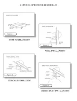
Page 38: ...MOUNTING OPTIONS FOR REMOTE FANS ...

Page 39: ...e Figure 5 C 2 When installing a remote fan on a flat roof or a roof with a pitch less than 1 in 12 inches install the remote fan in such a way that the discharge the lowest portion of the curb is directed away from any prevailing winds 3 When installing a remote fan on a roof or outside wall direct the discharge the lowest portion of the curb pointing down the slope as this is in accordance with ...

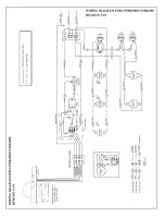
Page 40: ...s to the remote fan using color coded wires corresponding to color codes in diagram see Figure 7 Page 6 4 Locate the white plastic Moldex electrical connector in the hood This connector feeds the power to the remote fan Use the receptacle connector provided with the fan and plug to the connector in the hood Within the J box connect the black white red and blue wires from the remote fan to the blac...

Page 41: ...black white and green from the power supply at the electrical circuit panel to the wall box see Figure 7 4 Run electrical conduit per local code from wall box to bottom of remote fan as shown see Figure 7 5 Run five 14 AWG wires in conduit between ventilator J box and 4 position switch Use color coded wires corresponding to colors shown see Figure 7 6 Use wire nuts to connect wires as shown see Fi...

Page 42: ......

Page 43: ...or longer runs 7 Sheet metal screws are provided for L bracket attachment to the housing Screws must be positioned within 1 of the edge of the housing 8 Seal all ducting connections with cold weather metal tape 9 The unit should be hung on the L brackets using wood screws not provided 10 Rubber padding may be added to the insulation of the unit to reduce eliminate potential vibrations not provided...

Page 44: ...s for horizontal mounting 4 Install additional blocking to mount under the roof rafter 5 Install additional cross members to ceiling joists with a 90 degree elbow to exit side Important Notes Adding plywood to each installation may simplify install 10 diameter ducting is recommended for optimal performance of this product 8 diameter may be used if ducting space is limited but this may reduce the u...

Page 45: ...INSTALLATION SPECIFICATIONS ...

Page 46: ......

Page 47: ...d be as short and as straight as possible When turns are necessary keep turning radius as large and as smooth as possible WARNING TO REDUCE THE RISK OF A RANGE TOP GREASE FIRE a Never leave surface units unattended at high settings Boil overs cause smoking and greasy spillovers that may ignite Heat oils slowly on low or medium settings b Always turn hood ON when cooking at high heat or when flamin...

Reviews: