9
STEP 5
STEP 6
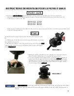
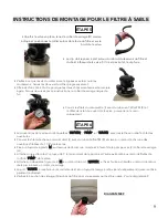
• The valve ports are labeled
“RETURN”
,
“PUMP”
, and
“WASTE”
with raised letters next to the openings.
• Cover the threads of each straight fitting
(J)
with Teflon
TM
tape
(K)
and thread one fitting into each of the
1-1/2” threaded openings on the valve.
• Attach a 6’ hose
(M)
to the bottom of the thru-wall skimmer and to the front of the pump with
(2)
hose clamps
(H)
.
• Clamp one end of a 3’ hose
(L)
to the top of the pump and the other end to the threaded fittings on the
“PUMP”
port of the valve.
• Attach a second 6’ hose
(M)
to the fitting on the
“RETURN”
port and secure the opposite end to the fitting
on the pools return with a clamp.
•
“WASTE”
port will accept a standard fitting and a backwash hose (sold seperately) which will be used during
maintenance.
• Check the drain plug
(N)
at the bottom of the filter to ensure that it is screwed on tight. See
Diagram 9
.
ASSEMBLY INSTRUCTIONS FOR SAND FILTER (CONT.)
• Once the valve is in place, hold the clamp
(D)
as shown and position
the clamp around the lip of the filter and over the edge of the valve.
• The clamp should sit flat around the lip of the filter tank and the
bottom edge of the valve. If it is not sitting flat, the clamp will leak.
• Make sure that the screws of the clamp are lined up with the seams
of the tank. Tighten two screws on the clamp: a little at a time.
Alternating from side to side so that both sides are tightened equally.
Failure to follow these instructions will result in leaking of the clamp.
• Cover the threads of the pressure gauge
(I)
with Teflon
TM
tape
(K)
and
thread into the open hole on the valve and hand tighten only.
DIAGRAM 9


