background image

 
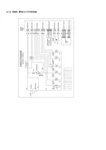
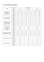
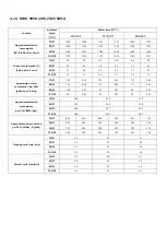
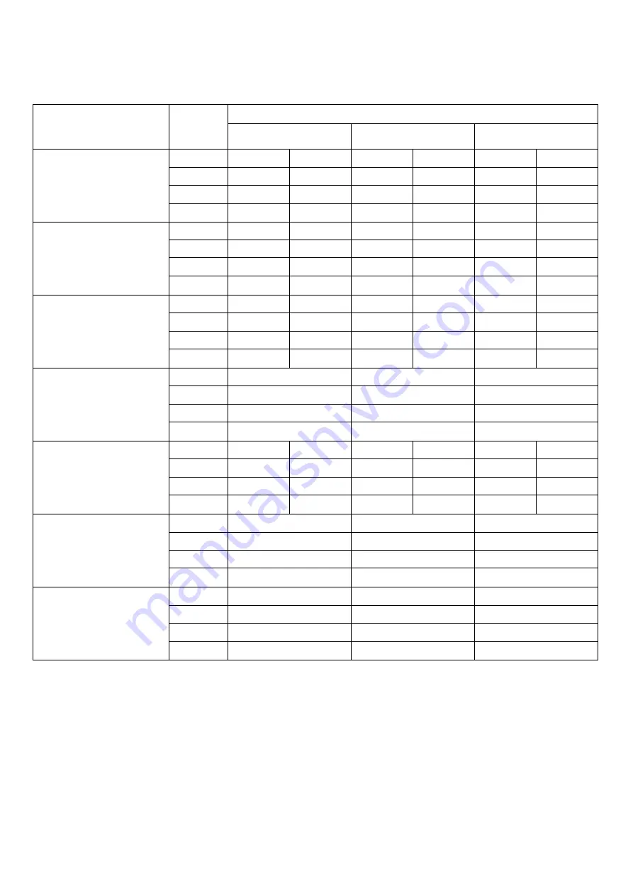
4.2.3


  BLMI-650A (208-230V/60Hz) 


content 

Ambient   

Temp 

(

º

F/

º

C) 

Water temp(

º

F/

º

C) 

50

º

F/10

º

70

º

F/21

º

90

º

F/32

º

Approximate electric 

consumption 

[W] (Stable after 5 min) 

70/21 

1102   

1071   

1080   

1015   

1164   

1024   

80/27 

1139   

1096   

1177   

1129   

1226   

1105   

90/32 

1213   

1199   

1280   

1186   

1331   

1188   

100/38 

1305   

1281   

1356   

1279   

1428   

1290   

Current consumption [A] 

(Stable after 5 min) 

70/21 

4.9   

4.7   

5.0   

4.7   

5.1   

4.9   

80/27 

5.1   

5.1   

5.4   

5.1   

5.6   

5.1   

90/32 

5.5   

5.4   

5.8   

5.5   

6.0   

5.5   

100/38 

5.9   

5.7   

6.2   

5.7   

6.5   

5.9   

Approximate water 

consumption per 24hr 

[gal/day, m^3/day) 

70/21 

89   

0.34   

89   

0.34   

86   

0.33   

80/27 

85   

0.32   

85   

0.32   

78   

0.30   

90/32 

80   

0.30   

76   

0.29   

73   

0.28   

100/38 

72   

0.27   

67   

0.25   

67   

0.25   

Approximate electric 

consumption 

per 24hr [kWh/day] 

70/21 

24.0   

24.7   

24.7   

80/27 

25.2   

26.4   

26.7   

90/32 

27.1   

27.3   

28.6   

100/38 

29.2   

30.0   

30.6   

Approximate ice production 

per 24hr [Ib/day , kg/day] 

70/21 

625   

283   

611   

277   

592   

269   

80/27 

593   

269   

541   

246   

519   

236   

90/32 

545   

247   

535   

243   

465   

211   

100/38 

453   

206   

450   

204   

416   

189   

Freezing cycle time [min] 

70/21 

29   

30   

32   

80/27 

31   

32   

35   

90/32 

34   

35   

38   

100/38 

38   

41   

42   

Harvest cycle time[min] 

70/21 

4.8   

3.8   

3.3   

80/27 

4.3   

3.4   

3.2   

90/32 

4.0   

3.3   

3.2   

100/38 

4.0   

3.3   

3.2   


Summary of Contents for BLMI-300A

Page 1: ...SERVICE MANUAL BLMI 300A BLMI 500A BLMI 650A BLMI 900A Ver200626 ...

Page 2: ...pe connection 1 6 Assembly structure 1 7 Specifications 2 Technical information 2 1 Water and refrigeration system 2 2 Operation 2 3 Control board 3 Troubleshooting 3 1 Parts operation check 3 2 How to update main control board program 3 3 Error codes 4 Circuit diagrams and technical data 4 1 Circuit diagrams 4 2 Performance data 4 3 Evaporator sensor data ...

Page 3: ...ice machine must be potable and of food grade quality High pressure refrigerant is charged into the ice machine Be careful not to damage the refrigerant circuit during installation maintenance and service Remove remaining water on the bottom side of the ice machine and any other things may cause danger before installation maintenance and service Turn off the power and disconnect electrical connect...

Page 4: ... C a 4 digits CIS code for specific model b 1 digit Product group c 2 digits Manufacturing site supplier code d 1 digit Manufacturing year e 1 digit Manufacturing month f 5 digits Serial number 00001 99999 BLMI 500A B Blue Air on US model only L Lassele Our brand in S Korea M Modular or U Undercounter I Crescent shaped ice Daily ice Production in LBS A Air cooled W Water cooled D Dispenser ...

Page 5: ...t edges of modular head and ice storage bin level and in alignment Is the air vent pipe for the machine and drain line for ice storage bin separated Is there an air gap at the end of the drain pipe of the ice storage bin Have the modular head and ice storage bin been checked and cleaned after installation Is the drain pipe easily disconnected from the modular head Is there 8 200mm minimum clearanc...

Page 6: ...2 50mm vertical clearance between drainage pipe end and drainage hole Drain outlet 3 4 FPT Shut off valve Copper pipe Minimum ID 1 4 Drain valve Vent tube Hard pipe Minimum ID 3 4 Bin drain outlet 3 4 FPT Steam outlet 3 8 OD hard tube Water supply inlet 3 8 FPT Floor drain ...

Page 7: ...ssembly structure 1 BLMI 300A BLMI 500A Evaporator Spray Tube Water inlet Valve Cleaning Valve Level Sensor Water Pump Control box Liquide Valve Compressor Drier Fan Motor Condenser Hot gas Valve Bin control ...

Page 8: ... Evaporator Spray Tube Water inlet Valve Cleaning Valve Level Sensor Water Pump Control box Liquide Valve Compressor Drier Fan Motor Condenser Hot gas Valve Bin control Main Transformer only for 208 230V 60Hz unit ...

Page 9: ... Main Transformer only for 208 230V 60Hz unit Evaporator Spray Tube Water inlet Valve Cleaning Valve Level Sensor Water Pump Control box Liquide Valve Compressor Drier Fan Motor Condenser Hot gas Valve Bin control ...

Page 10: ...30lbs Per Cycle lb Cubes 6 64 lb 2 9 Kg 360 EA 9 83 lb 4 45 Kg 480 EA Refrigerant R 410A R 410A Content BLMI 650A BLMI 900A REMARKS AC Supply voltage 208 230 V 60Hz 1Ph for 115V 208 230 V 60Hz 1Ph for 115V Amperage power onsumption 9 0A 1186W 9 0A 1133W AT90 WT70 AT32 WT21 Maximum Fuse Circuit Breaker 15A 15A Product size W D H 22 27 3 8 37 3 4 inch 558 W 696 D 958 H mm 30 27 3 8 37 3 4 inch 762 W...

Page 11: ...rmation 2 1 Water and refrigerant system Refrigerant Circuit Water Circuit Comp Water Pump Spray Tube Level Sensor Evaporator Supply Tube Overflow Hot gas V V Exp V V Liquide V V Fan Motor V V Water inlet V V Check V V ...

Page 12: ...p On HGV On LV Off FM Off PM Off WV On WV On HGV On THRMISTOR 7 PM On Thermistor 1 reaches PM 15s Off Ice Seonsor in control Power On Comp On HGV Off LV On FM On PM On WV Off FS Open LS Open Comp On HGV On LV Off FM Off PM Off DV On Or PM On MAX 25 min MAX 60 min Comp Compressor HGV Hot Gas Valve LV Liquie Valvve FM Fan Motor PM Pump Motor WV Water Valve LS Level Sensor DV Deain Valve ...

Page 13: ...storage bin is full s Bin Full DRAIN CYCLE Bin Full WATER FILL CYCLE 5 min DV Off Or PM Off DV On Or PM On WV On HGV On Comp On HGV On LV Off FM Off PM Off WV On Comp Off HGV Off LV Off FM Off PM Off WV Off LS Close ...

Page 14: ... Simply multiply by 10 and you will have the exact number of seconds the water cycle has been active Harvest The action of dropping a batch of ice from the evaporator into the bin is called the Harvest cycle The ice machine continues to repeat harvest and freezing cycles except for the first time the machine is turned on The compressor hot gas valve and water valve are in operation during the harv...

Page 15: ...le The drainage interval last from 10 20 seconds Regular drainage time and interval can be adjusted upononce the water conditionconditions are ascertained at the site of installation place The ice machine will go into the drainage interval if the ice storage bin is full for five minutes to prevent contamination of water inside the water tank Full storage If the bin switch senses the bin is full of...

Page 16: ...Y 4 EC 3 EC 2 REG 1 HS 1 D10 EC 1 CN 5 CN 1 Compressor BD 1 CN 7 CN 11 CN 6 CN 3 CN 4 XC 2 LF 1 VA 1 XC 1 VA 6 VA 7 VA 2 VA 3 VA 4 CN 13 CN 5 VA 5 Liquid V V Cleaning V V Water Pump C C W Water V V Fan Motor Hat Gas V V Water Pump C W Compressor Power Bin Sensor Float Switch Evaporator Sensor Control PCB ...

Page 17: ...ater supply cycle for 20 seconds 2 Harvest cycle xx Elapsed time x 1 minute Ex 2 02 In harvest cycle for 20 seconds 3 Freezing cycle xx Elapsed time x 1 minute Ex 3 02 In freezing cycle for 20 seconds In drainage cycle In cleaning cycle Need to add cleaner or sanitizer Cleaning cycle is completed Status LED lamp Display Buttons ...

Page 18: ...splayed if the same situation happens again E3 If evaporator sensor temperature is over 60 140 E4 The ice machine automactically drains 5 minutes after the bind is full E4 will be displayed if the water is not drained for 480 seconds E5 1 For the first ice making cycle If the float switch does not sense enough water at the end of the first water supply cycle the ice machine will go back to the wat...

Page 19: ... these buttons will force the machine into the harvest cycle Power Check Pressing and holding these buttons will force the drainage cycle Wash Check This will open the hot gas valve and water valve to aid in the system evacuation in the lines if necessary Status check Once the check button is pressed the display will cycle through the status of each of the categories below Simply press check again...

Page 20: ...displayed 3 Press check button again to adjust P 1 setting result The setting can be adjusted up or down by pressing power or wash buttons 4 P 2 after pressing the check button again P 2 will be displayed 5 Refer to following table to check each parameter s meaning and further information 6 Press check button for five seconds to get out of the parameter setting mode ...

Page 21: ...ime 0 30 1 min 12 P 12 Set tempearture display unit 13 P 13 Set hertz 50 60 hz P 1 Set evaporator temperature for harvest control Once evaporator sensor reaches the set temperature harvest cycle will be done Default Setting 7 44 6 P 2 Set harvest delay time after evaporator sensor reaches a set temperature Default 7 44 6 for harvest Default harvest delay time depends on model P 3 Set drainage cycl...

Page 22: ...hen a unit will need to have new filtration and also how long the unit has been in operation This acts like the the ice machine odometer P 9 Set drainage time Default 10 seconds P 10 Set water supply time during harvest P 11 Set minimum freezing time to prevent the evaporator from freezing while the ambient temperature is low Default setting depends on model P 12 Set temperature unit either or P 1...

Page 23: ... seconds 2 Press and hold wash button for 5 seconds to activate test mode 3 Off will be displayed 4 C will be displayed The compressor will turn on to show the compressor is working 5 To cycle through all the working parts of the machine simply press the wash button again Refer to the table below for further information 6 To exit the test mode press and hold wash button when off is displayed on th...

Page 24: ...n Drainage 5 H Hot gas valve On 6 F Fan motor On 7 E Water valve On 8 AC Cleaning valve On 9 AS Liquid valve On 10 d Drain On 11 Dyc Water valve on Factory use only Cleaning valve on Drain valve on The test mode only shows available parts for each machine If the ice machine does not have a certain part the test code for that part will not show up on the display ...

Page 25: ... disappear within 5 seconds after releasing the plate flap 2 Water level sensor Can be checked while the machine is in operation Water supply Freezing or Harvesting Cycle Lift the float switch to its highest level and then proceed to slowly push the float switch all the way down to the lowest position The display will show a green light to indicate the float is at the lowest position A Red light w...

Page 26: ... machine must be connected to main power for update Connect Pick it 3 to potable battery pack Conncet Pick it 3 to reset pin referring to above image Reset pin connector on Pick it 3 and reset pin on main PCB must be properly matched Press button on Pick it 3 Beep alarm will sound when update is done Writing pin Reset pin Reset pin connector Button Pick it 3 ...

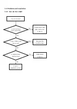
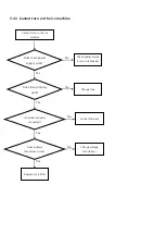
Page 27: ...Compressor Replace parts Refrigerant pipe line is clogged Replace it No Yes No Is the ice too small Is the water level sensor properly assembled and working No Replace reassemble water level sensor or clean it No Yes Check drainage pipe if it is overflowing while the water tank is full Yes Is pump motor thermal protector working No Yes Check environmental conditions Ambient and water temperature 1...

Page 28: ... for leaks repair and recharge refrigerant Yes Is the evaporator sensor properly insulated Yes Proceed with evaporator sensor temperature correction P 4 No Are environmental conditions within specification No Change installation place Yes Does hot gas valve work No Replace valve coil Yes Is the PCB program latest version No 1 Replace main PCB 2 Update program Yes Refrigerant pipe line is clogged R...

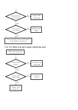
Page 29: ...tallation place Yes 센서가 실제온도 와 같은가 No Replace sensor Yes Insulate evaporator sensor Water is not sufficiently drained within set drainage time default 480 seconds when the ice storage bin is full Is the water drained No Connect the drainage line Is the drainage line inside of the ice machine properly connected No Yes Is the water drained while test mode Replace parts related to drainage No Yes Rep...

Page 30: ...ump motor installed No Check drainage line outside of the ice machine Air vent installation and hose size Yes Replace pump motor Water level sensor keeps catching low water level Is water properly supplied No Check water supply pipe and valve Yes Is supplied water pressure okay No Adjust water pressure Yes Replace water level sensor ...

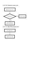
Page 31: ...vaporator sensor error 3 3 7 E7 Main PCB program error Evaporator sensor error Is the sensor properly connected Connect sensor No Yes Sensor is damaged Replace sensor or harness E7 is showing up Repalce main PCB ...

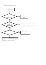
Page 32: ...o small Is water level sensor properly assembled Yes No Replace reassemble water level sensor or clean it Is water drained during freezing cycle No Re assemble overflow pipe Yes Adjust water pressure Is supplied water pressure okay No Yes Check if evaporator is bent ...

Page 33: ...tion place No Is drainage line properly assembled Yes Check drainage line outside of the ice machine Air vent installation and hose size No Yes Set longer harvest delay time by using P 2 on parameter setting instruction Is the PCB program latest version Yes 1 Replace main PCB 2 Update program No ...

Page 34: ...e machine Does main power supply work Check power source and circuit breaker No Does fuse properly work Change fuse No Is harness properly connected Connect harness No Yes Yes Does voltage transformer work Yes Change voltage transformer No Yes Replace main PCB ...

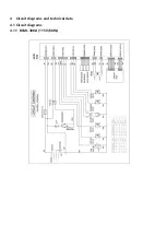
Page 35: ...4 Circuit diagrams and technical data 4 1 Circuit diagrams 4 1 1 BLMI 300A 115V 60Hz ...

Page 36: ...4 1 2 BLMI 500A 115V 60Hz ...

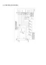
Page 37: ...4 1 3 BLMI 650A 208 230V 60Hz ...

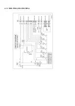
Page 38: ...4 1 4 BLMI 900A 208 230V 60Hz ...

Page 39: ...Approximate water consumption per 24hr gal day m 3 day 70 21 36 0 14 35 0 13 34 0 13 80 27 31 0 12 31 0 12 30 0 11 90 32 28 0 11 27 0 10 26 0 10 100 38 23 0 09 22 0 08 22 0 08 Approximate electric consumption per 24hr kWh day 70 21 12 4 12 7 12 8 80 27 13 4 13 6 13 7 90 32 14 2 14 3 14 5 100 38 15 4 15 4 15 4 Approximate ice production per 24hr Ib day kg day 70 21 340 154 326 148 317 144 80 27 293...

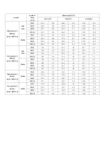
Page 40: ...er 5min 70 21 73 3 5 2 91 7 6 5 95 3 6 7 80 27 87 5 6 2 96 7 6 8 101 0 7 1 90 32 98 9 7 0 103 8 7 3 108 8 7 7 100 38 106 7 7 5 112 4 7 9 117 3 8 3 Stable 70 21 56 9 4 0 60 4 4 3 61 2 4 3 80 27 62 6 4 4 63 3 4 5 65 4 4 6 90 32 65 4 4 6 65 4 4 6 68 3 4 8 100 38 67 6 4 8 68 3 4 8 69 0 4 9 High pressure in harvest psig kgf g Stable 70 21 148 6 10 5 177 8 12 5 189 2 13 3 80 27 158 6 11 2 182 1 12 8 192...

Page 41: ...oximate water consumption per 24hr gal day m 3 day 70 21 73 0 28 68 0 26 68 0 26 80 27 67 0 25 63 0 24 62 0 23 90 32 60 0 23 61 0 23 55 0 21 100 38 52 0 20 51 0 19 48 0 18 Approximate electric consumption per 24hr kWh day 70 21 19 6 20 3 20 8 80 27 21 2 22 0 22 4 90 32 22 9 23 1 23 9 100 38 25 0 25 5 26 1 Approximate ice production per 24hr Ib day kg day 70 21 538 244 524 238 486 221 80 27 497 225...

Page 42: ...fter 5min 70 21 74 8 5 3 78 5 5 5 84 6 5 9 80 27 83 3 5 9 87 8 6 2 96 3 6 8 90 32 89 5 6 3 98 0 6 9 103 1 7 3 100 38 93 7 6 6 97 3 6 8 121 6 8 6 Stable 70 21 54 0 3 8 54 0 3 8 55 5 3 9 80 27 54 8 3 9 57 4 4 0 86 8 6 1 90 32 60 2 4 2 78 2 5 5 96 7 6 8 100 38 72 1 5 1 95 8 6 7 111 4 7 8 High pressure in harvest psig kgf g Stable 70 21 163 6 11 5 184 9 13 0 215 1 15 1 80 27 167 1 11 8 195 8 13 8 224 ...

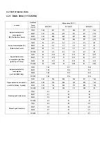
Page 43: ...9 Approximate water consumption per 24hr gal day m 3 day 70 21 89 0 34 89 0 34 86 0 33 80 27 85 0 32 85 0 32 78 0 30 90 32 80 0 30 76 0 29 73 0 28 100 38 72 0 27 67 0 25 67 0 25 Approximate electric consumption per 24hr kWh day 70 21 24 0 24 7 24 7 80 27 25 2 26 4 26 7 90 32 27 1 27 3 28 6 100 38 29 2 30 0 30 6 Approximate ice production per 24hr Ib day kg day 70 21 625 283 611 277 592 269 80 27 5...

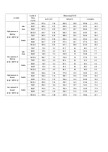
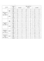
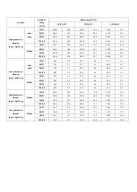
Page 44: ... after 5min 70 21 77 5 5 5 82 3 5 8 85 7 6 0 80 27 79 0 5 6 83 3 5 9 92 8 6 5 90 32 81 6 5 7 89 8 6 3 99 6 7 0 100 38 82 4 5 8 91 6 6 4 101 4 7 1 Stable 70 21 56 9 4 0 58 3 4 1 59 7 4 2 80 27 60 4 4 3 60 4 4 3 63 1 4 4 90 32 64 0 4 5 64 5 4 5 65 4 4 6 100 38 64 5 4 5 67 8 4 8 83 1 5 8 High pressure in harvest psig kgf g Stable 70 21 158 6 11 2 162 1 11 4 209 1 14 7 80 27 161 4 11 4 179 9 12 7 217 ...

Page 45: ...pproximate water consumption per 24hr gal day m 3 day 70 21 125 0 47 124 0 47 122 0 46 80 27 116 0 44 112 0 43 111 0 42 90 32 108 0 41 97 0 37 96 0 36 100 38 94 0 36 92 0 35 90 0 34 Approximate electric consumption per 24hr kWh day 70 21 29 8 30 5 31 0 80 27 32 5 33 4 33 8 90 32 34 6 34 7 36 2 100 38 38 0 38 3 38 9 Approximate ice production per 24hr Ib day kg day 70 21 890 404 868 394 853 387 80 ...

Page 46: ...after 5min 70 21 68 3 4 8 69 7 4 9 77 3 5 4 80 27 72 5 5 1 81 1 5 7 86 8 6 1 90 32 77 8 5 5 82 5 5 8 88 9 6 3 100 38 88 7 6 2 89 6 6 3 89 6 6 3 Stable 70 21 51 7 3 6 51 7 3 6 52 2 3 7 80 27 54 0 3 8 54 5 3 8 55 5 3 9 90 32 56 9 4 0 56 9 4 0 56 9 4 0 100 38 60 7 4 3 61 2 4 3 61 2 4 3 High pressure in harvest psig kgf g Stable 70 21 236 1 16 6 250 3 17 6 272 6 19 2 80 27 240 4 16 9 266 9 18 8 287 3 ...

Page 47: ...6 7 01 56 1 78 96 0 582 23 37 2 17 6 75 57 1 72 97 0 568 22 35 5 18 6 50 58 1 67 98 0 554 21 33 9 19 6 26 59 1 62 99 0 540 20 32 3 20 6 03 60 1 57 100 0 527 19 30 8 21 5 80 61 1 53 101 0 514 18 29 4 22 5 59 62 1 48 102 0 501 17 28 1 23 5 39 63 1 44 103 0 489 16 26 8 24 5 20 64 1 40 104 0 477 15 25 6 25 5 01 65 1 35 105 0 466 14 24 5 26 4 83 66 1 32 106 0 455 13 23 4 27 4 66 67 1 28 107 0 444 12 22...

Reviews: