System Description Party Line Telephone System PLTS
BCPT1010.SD.E2.doc, Version 1.0
BlueCom AG, 1.3.1999
14
7 Installation
7.1 Unpacking and Inspection
After Unpacking the unit, retain the carton and packing materials until the contents have
been inspected and checked against packing list. If there is a shortage or any evidence of
damage, do not attempt to use the equipment. Contact the carrier and file a shipment
damage claim. A full report of the damage should also be reported to BlueCom AG. The
following information should be included in the report:
Order number
Equipment Model and Serial Numbers
Shipping Agency
Date of Shipment
The BlueCom Service Department can be reached by phone at ++41 1 748 48 18 and by
Fax ++41 1 748 48 19. Upon receipt of this information BlueCom will arrange for repair or
replacement of the equipment.
7.2 Installation Overview
The following steps are needed to properly install the PLTS System:
Provide mechanical mounting for the unit. The Rack R7AH can be installed in a standard 19’’
cabinet by its front panel.
Provide the proper primary power for the bridging amplifiers J3KA.
Connect the SETEL phones to the V9CT cables.
Interconnect the unit with the communication system via the V9CT cable delivered with each
bridging amplifier J3KA.
7.3 Installation Considerations
Careful attention to the following installation suggestions should result in the best unit/system
performance.
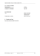
The PLTS system must be installed in an environment, which provides both protection from
the weather and assurance of ambient temperatures between 0 and 55 degrees C. Since the
unit is neither splashproof nor corrosion resistant, it must be protected from exposure to salt
spray. When the unit is mounted in a cabinet with other heat-generating equipment, keep 1
HE free air space above and below the R7AH rack.
7.4 DC-Power Requirements:
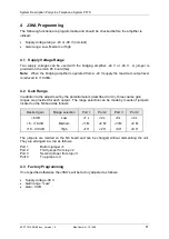
The J3KA will be delivered from the factory with the supply jumper set to 48V DC. The J3KA
Amplifiers operate on a 48V DC or 24V DC power supply. First check right jumper setting.
Following voltage range has to be met:
Jumper on 48V DC:
-40 ... –60V
Jumper on 24V DC:
-20 ... –30V
If the input voltage exceeds the maximum voltage stated above it may result in damage of
the equipment. Power consumption of each J3KA is less than 5W.
7.5 External Interconnect Information
Please find on the standard drawing BC980117 a typical wiring configuration.


