
•
Posi head hand screwdriver
•
Marine sealant 3M 5200/4000UV, Sika flex 291i or equivalent (
do not use 3M 4200
)
Installation:
For optimum affect effect the light should be positioned between 8-
12” (200
-300mm) below the
water line and at a 90 deg angle. Recommended spacing from 3-
3”(1mtr) to 5
-
11” (1.8mtrs) between
the lights.
Drill a 30mm (1.1/4
”)
hole for the cable access through the hull, ensuring that there are no
obstructions internally in the hull.
Drill 2.5mm(3/32
”)
pilot holes to match the mounting holes on the light.
Key the area to where the light is to be mounted with abrasive sand paper to ensure there is a clean
area for the marine sealant to bond too.
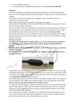
Apply marine sealant to the rear of the light on the circumference of the light and around the base of
the cable gland to ensure a complete continuous bead of sealant is applied in both areas. (See fig 2)
Feed the cable through the hole and mount the light to the hull using the
screws provided
.
Wipe off any excess sealant and ensure the light is seated correctly without any gaps in the sealant.
(It is good practice to have excess marine sealant to clean off as this can ensure that there is a water
tight seal to the hull)
Electrical connection:
It is advised that if installing H20 and H48CC Models no more than 6 lights should be installed on
your low voltage system and Mains Power Units should be installed (contact BluefinLED for
advice).
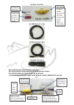
Ensure you use the IP68 GEL CONNECTOR supplied to connect to the boats wiring or you Warranty
will be void (fig 4/5).
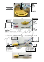
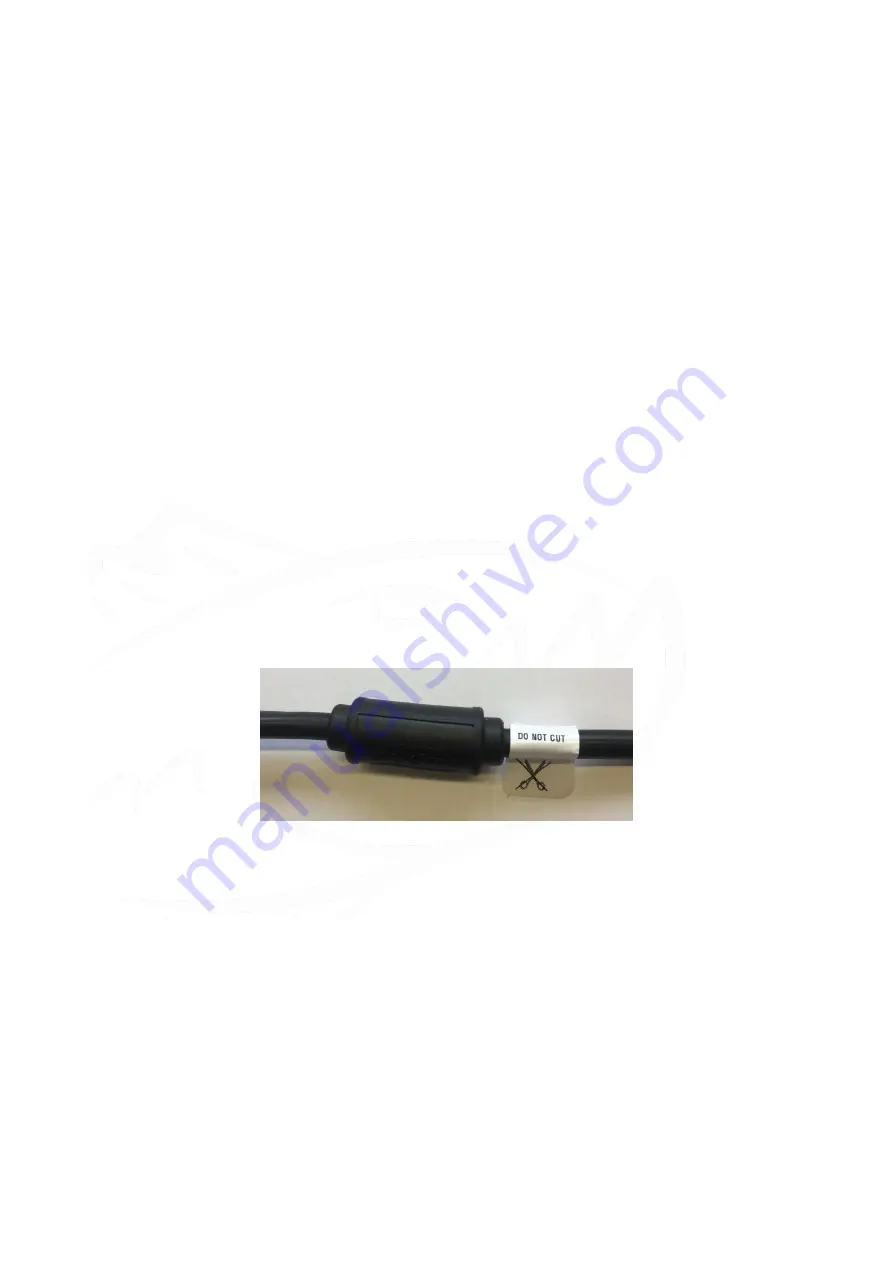
You will notice an inline HYDRO LOCK attached to your cable (Fig 1). If this guard is removed you
warranty will be void
Pic 1
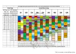
Care should be taken when planning your electrical feeds/cables to the lights so as to ensure voltage
drop between the batteries or power supply is minimised, on 12V systems this is especially important
as the lower system voltage means a high current requirement which in turn means the potential for
more voltage drop in the cable runs & connections.
If the cable gauge & connections are not sufficient for the lighting load attached you may experience
incorrect operation of the lights & intermittent illumination as the supply dips below specification.
Please see the wire gauge guide attached to the instruction manual.
For help with calculations always consult with a qualified professional or contact BluefinLED directly.
Attach the light cable to the VDC power on the boat ensuring that you use the in line fuse supplied
connected to the positive(red) wire, ensure that you use the heatshrink provided to create a water
tight fit into the fuse holder. (See fig 3)
Ensure that an earth bond cable is attached to the earth tab on the cable gland using the nuts and
bolts supplied and is attached to the earth bonding system on the boat before installation. Please
also bend the earth bond tab into the horizontal position as per fig 1