
2
Installation:
Before installation please ensure the red line is horizontal (the label is fitted to the face of the
light), this is to ensure you install the light perpendicular to the water line. Ensure that all lights are
fitted the same. If the lights are not all orientated the same way the light will not appear even
(different angles) in the water (see fig 6)
For optimum affect effect the light should be positioned between 8-12” (200-300mm) below the
water line and at a 90 deg angle. Recommended spacing from 1.65 ft(0.6mtr) to 4.92ft (1.5mtrs)
between the lights.
Drill a 17mm (17/25”) hole for the cable access through the hull, ensuring that there are no
obstructions internally in the hull.
Drill 2.5mm ( 3/32”)pilot holes to match the mounting holes on the light. (Within the packaging there
is a mounting template for drilling these holes)
Key the area to where the light is to be mounted with abrasive sand paper to ensure there is a clean
area for the marine sealant to bond to.
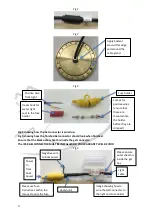
Apply marine sealant to the rear of the light on the circumference of the light and around the base of
the cable gland to ensure a complete continuous bead of sealant is applied in both areas. (see fig 2)
Feed the cable through the hole and mount the light to the hull using the
screws provided
.
Wipe off any excess sealant and ensure the light is seated correctly without any gaps in the sealant.
(It is good practice to have excess marine sealant to clean off as this will help assure a water tight
seal to the hull)
Electrical connection:
Ensure you use the IP68 GEL CONNECTOR supplied to connect to the boats wiring or you Warranty
will be void (fig 4/5).
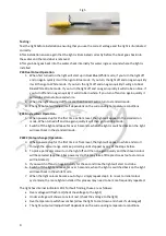
You will notice an inline moisture guard attached to your cable (Fig 1). If this guard is removed your
Warranty will be void.
Care should be taken when planning your electrical feeds/cables to the lights so as to ensure voltage
drop between the batteries or power supply is minimised, on 12V systems this is especially important
as the lower system voltage means a high current requirement which in turn means the potential for
more voltage drop in the cable runs & connections.
If the cable gauge & connections are not sufficient for the lighting load attached you may experience
incorrect operation of the lights & intermittent illumination as the supply dips below specification.
Please see the wire gauge guide attached to the instruction manual.
For help with calculations always consult with a qualified professional or contact Bluefin LED directly.
Attach the light cable to the VDC power on the boat ensuring that you use the GEL CONNECTOR and
in line fuse supplied connected to the positive(red) wire, ensure that you use the heat shrink
provided to create a water tight fit into the fuse holder. (see fig 3)
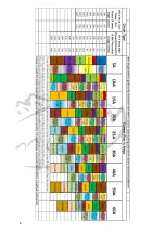
P24 Dual and CC Colour Only
When installing P24 Dual Colour and Colour change lights it is advised to wire the lights up to a single
switch so that all of the lights operate in sequence with each other. It is also advised that you choose
an appropriate switch that has the correct power rating for the amount of lights being installed
(please see the P24 Dual Colour current values above).
Summary of Contents for P24
Page 6: ...6...


