background image

14

Fixed Omni Antennas

Compliance

Electrical/Safety

UL 60950


CAN/CSA-C22.2


IEC 60950


EN 60950 

Radio Signal Certification

FCC Part 15.247, 15.407 


RSS-210 (Canada) 


EN 300.328, EN 301.893 (Europe)

FCC Radiation Exposure Statement

This equipment complies with FCC radiation exposure limits set forth for an uncontrolled 

environment. This equipment should be installed and operated with a minimum distance of 

20 centimeters (8 inches) between the radiator (antenna) and your body.
This transmitter must not be co-located or operating in conjunction with any other antenna 

or transmitter.

Federal Communication Commission Interference Statement

This equipment has been tested and found to comply with the limits for a Class B digital 

device, pursuant to Part 15 of the FCC Rules. These limits are designed to provide 

reasonable protection against harmful interference in a residential installation. This 

equipment generates, uses and can radiate radio frequency energy and, if not installed 

and used in accordance with the instructions, may cause harmful interference to radio 

communications. However, there is no guarantee that interference will not occur in a 

particular installation. If this equipment does cause harmful interference to radio or 

television reception, which can be determined by turning the equipment off and on, the 

user is encouraged to try to correct the interference by one of the following measures:
-

Reorient or relocate the receiving antenna.

-

Increase the separation between the equipment and receiver.

-

Connect the equipment into an outlet on a circuit different from that to which the 

receiver is connected.

-

Consult the dealer or an experienced radio/TV technician for help.

This device complies with Part 15 of the FCC Rules. Operation is subject to the following 

two conditions: (1) This device may not cause harmful interference, and (2) this device 

must accept any interference received, including interference that may cause undesired 

operation.
FCC Caution: Any changes or modifications not expressly approved by the party 

responsible for compliance could void the user's authority to operate this equipment.
For operation within 5.15 ~ 5.25GHz frequency range, it is restricted to indoor 

environment.

Antenna

Model

Antenna

Type

Antenna

Connector Type

FDSI3W 


FDSI3W

Dipole

MMCX Connector

Summary of Contents for BlueSecure 1540

Page 1: ...BlueSecure Access Point 1540 Installation Guide Bluesocket Inc 10 North Avenue Burlington MA 01803 USA 1 781 328 0888 www bluesocket com Part Number 873 01540 M00 Document Version 1 0...

Page 2: ...lity fitness for a particular purpose or non infringement This publication could include technical inaccuracies or typographical errors Changes are periodically added to the information herein these c...

Page 3: ...rnal Antenna Connectors 5 Provisioning Your Bluesocket WLAN for BSAPs 5 Deploying BSAPs on the Same Layer 2 Subnet as the BSC 6 Deploying BSAPs with Layer 3 Connectivity to the BSC 6 Selecting a BSAP...

Page 4: ...iv Contents...
Page 5: ...host BlueSecure Controller advanced configuration and provisioning may be applied either to individual BSAPs or globally across the entire WLAN using the BSC s web based Administrator Console Once a...

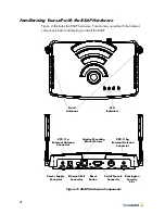
Page 6: ...components before attempting to install the BSAP Figure 2 BSAP Hardware Components Fixed Antennas LED Indicators Captive Mounting Bracket Screw Reset Button Power Supply Connector Ethernet PoE Connec...

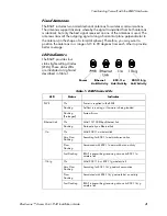
Page 7: ...EDs are illustrated at right and described in Table 1 Table 1 BSAP Status LEDs LED Status Indicates PWR On Power is supplied to the BSAP Flashing Self test is running or firmware is being loaded Flash...

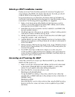
Page 8: ...u can therefore use straight through twisted pair cable to connect this port to most network interconnection devices such as a switch or router that provide MDI X ports However when connecting the BSA...

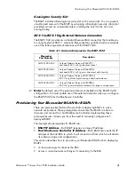
Page 9: ...erequisites ensure that the BSAPs are able to discover and connect to a host BlueSecure Controller Implementing these prerequisites also relieves you from the need to manually configure each deployed...

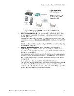
Page 10: ...on procedures In this deployment scenario simply connect and power on the BSAPs They will automatically discover and communicate with their home BSC Deploying BSAPs with Layer 3 Connectivity to the BS...

Page 11: ...rk with an entry for apdiscovery with the home BSC Controller IP address as the resolution To configure this add a NAME record to the DNS server for apdiscovery at the domain server that the BAP will...

Page 12: ...units bookcases and filing cabinets do not obstruct radio signals to and from the BSAP Define preliminary BSAP positioning based on the range of BSAPs and client devices which is approximately 65 to...

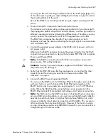
Page 13: ...3af compliant Power over Ethernet PoE Note If the BSAP is connected to both a PoE source device and an AC power source PoE will be disabled Caution Use only the power adapter supplied with the BSAP O...

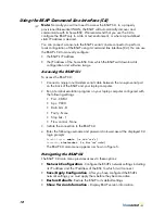
Page 14: ...en the nine pin serial port on the back of the BSAP and your laptop computer 2 Run a terminal emulation program on your laptop computer configured with the following settings Port COM1 bps 9600 Data b...

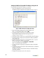
Page 15: ...nfiguration IP_ADDR_MODE DHCP 0 IP_ADDR 0 0 0 0 NETMASK 0 0 0 0 GW_ADDR 0 0 0 0 DNS_ADDR 0 0 0 0 WG_ADDR_MODE Discover BSC 0 WG_ADDR 0 0 0 0 The two options for IP address mode are 0 DHCP The BSAP run...

Page 16: ...o specify the BSAP s default IP gateway 5 Enter 4 at the Network Cfg prompt to specify the IP address of the BSAP s primary DNS server 6 Enter 5 at the Network Cfg prompt to specify the BSC mode i e h...

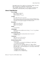
Page 17: ...vided and the adapter is plugged in PoE will be turned off Dimensions Length 9 75 in 24 17 cm Width 6 14 in 15 60 cm Height 1 56 in 3 96 cm Weight 1 5 lbs 0 68 kg LED Indicators PWR Power Ethernet Lin...

Page 18: ...to radio communications However there is no guarantee that interference will not occur in a particular installation If this equipment does cause harmful interference to radio or television reception w...

Page 19: ...to operate with an antenna having a maximum gain of 2 dB Antenna having a higher gain is strictly prohibited per regulations of Industry Canada The required antenna impedance is 50 ohms To reduce pot...

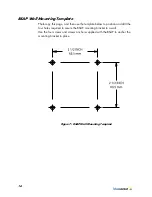
Page 20: ...en use the template below to position and drill the four holes required to secure the BSAP mounting bracket to a wall Use the four screws and screws anchors supplied with the BSAP to anchor the mounti...

Reviews: