All specifications are subject to change without prior notice
P/N 751001 Rev 1
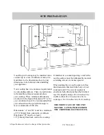
Your Drop-in Cooktop may be installed into a
counter top in a row of cabinets or into an is-
land. Refer to the illustration above for key
dimensions to be followed when installing
your appliance.
Your cooktop has zero clearance requirements
to surrounding surfaces. There are restrictions
to flammable surfaces around and above
your cooktop. These minimum dimensions
are shown in the figure. Dimension “E” is for
your ventilation hood. It is recommended that
your exhaust hood be powerful enough to
move a minimum of 300 cfm.
Dimensions “A” and “B” must be a minimum
of 6” [150mm] from side walls or cabinets.
Dimension “D” must be at least 1
1/2” [38mm] from back wall to the cooktop.
If installed in a countertop along a wall at the
rear the surface must be inflammable material
extending at least six inches upward.
When making the cut-out be sure to follow
the dimensions that match the body of your
cooktop model. The cut-out required is
smaller in both directions than the finished
top. The depth is always 20-1/4 inches. The
width is either 28-1/4 inches for a 30 in
cooktop or 34-1/4 inches for a 36 in cooktop.
SITE PREPARATION
THE FRONT FACE OF THE UNIT
MUST BE 2 (TWO) INCHES FROM
THE FRONTEDGE OF THE COUN-


