background image


- 47 - 

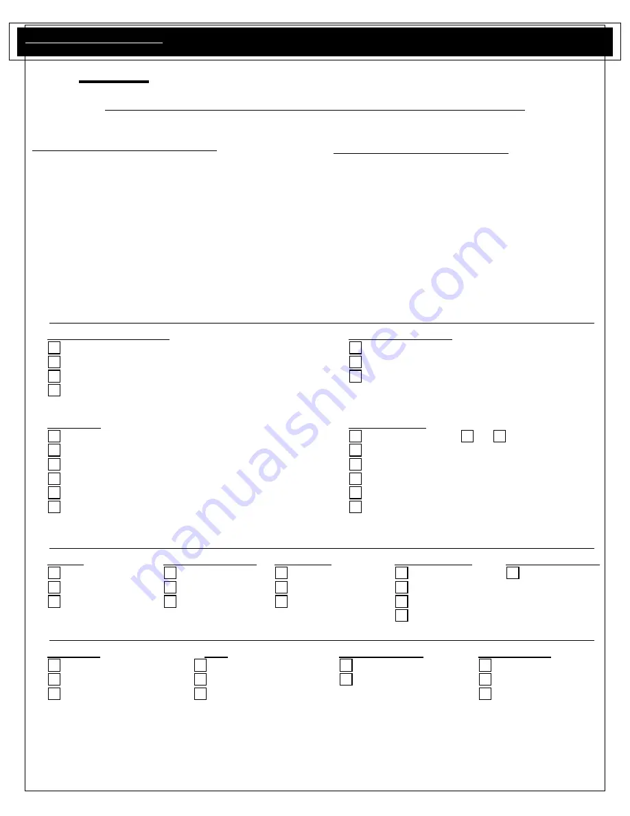
SAMPLE MANUFACTURERS’ PERFORMANCE CHECKLIST 

This checklist has been developed to assure proper installation of your range or cooktop as well as instruction on using this unit. 

To validate your warranty, you must mail or fax this form with a copy of your receipt to: 

 Warranty Department, 600 Arlington Street, Reading, PA 19611.  Fax: (610)376-2596 

Failure to perform these steps during installation could invalidate your warranty.


Customer Information 

(please print legibly)


Name: ________________________________________


Address:_______________________________________  
City___________________________________________  
State, Zip ______________________________________


E-mail: ________________________________________


Telephone #: ___________________________________


Selling Dealer: __________________________________  
Dealer Telephone:  ______________________________


Product Information 

(please print legibly)


Model: _________________________________________  
Serial #:________________________________________


Purchase Date:  _________________________________  
Delivery Date: ___________________________________  
Installation Date:_________________________________  
Installer’s Name:_________________________________  
Company Name:_________________________________  
Installer Telephone: ______________________________  


OVERALL UNIT 

Appearance & Aesthetics 

Electrical Connection 

Exterior 

(Plate Rail, Control Panel, Oven Door, Kick Panel)


Voltage 

(see pg. 5)


Oven Interior 

(Porcelain Finish, Oven Racks)


Ground 

(see pg. 5)


Top Section

 (Top Grates Ring Grates,Burners)


Polarization 

(see pg. 5)


Broiler Pan Set 


Installation Gas 

Connection 

Proximity to Cabinets 

(see pg. 7)


Verify Fuel Type:  Nat   LP  

Level 

(see pg. 8) 

Gas shut-off 

(present/accessible)


Ventilation System 

(see pg. 5)


Supply Line Size 

(see pg. 8)


Backguard 

(see pg. 6)


Supply Pressure 

(see pg. 8)


Use & Care Guide 

(see pg. 15)


Operating Pressure 

(see pg. 8)


Review Safety Instructions 

(see pg. 11)


Check All Gas Connections For Leaks 


COOKTOP/RANGE 

Ignition 

Flame Adjustments 

Air/Fuel Mix 

Valve Operation 

Thermostat Control 

Top Burners 

(see pg. 16)


Top Burners 

(see pg. 17)


Top Burners 

(see pg. 17)


Top Burners 

(see pg. 16)


Griddle 

(see pg. 21)


Griddle 

(see pg. 21)


Griddle 

(see pg. 21)


Griddle 

(see pg. 17)


Griddle 

(see pg. 21)


Charbroiler 

(see pg. 21)


Charbroiler 

(see pg. 21)


Charbroiler 

(see pg. 17)


Charbroiler 

(see pg. 21)


Knobs

(push to turn)


RANGE/OVEN 

    Controls 

    Door 

    Infrared Broiler 

    Oven Burner 

Convection fan & switch 

Alignment 

Ignition 

(see pg. 20)


Ignition 

(see pg. 18)


Interior light & switch 

Seal 

Proper Flame 

(see pg. 20)


Air/Fuel Mix

(see pg. 19)


Thermostats 

Hinges  

Temperature Check 

(If req’d)


I acknowledge that we, the installation technician and the consumer, have checked and verified each item. 


__________________________________________  

________________________________________ 

Consumer 

  Date 

   Installation 

Technician 

 Date


Attention Service Agent! The page numbers listed below refer to the installation manual, located with the unit! 

Summary of Contents for RNB 30

Page 1: ...RANGES COOKTOPS FOR THE HOME MODELS RNB 30 RPB 30 RGTNB 30 RNB 36 RPB 36 RGTNB 36 RNB 48 RGTNB 48 RNB 60 RGTNB 60 RCS 30 and RCS 36 Service Manual Free Standing Gas Range 600 Arlington Street Reading...

Page 2: ...nd meet and exceed our customer s expectations before during and after the service requirements that are performed on this quality product Our parts and service department has gone through great detai...

Page 3: ...Adjustment 23 Bake Broil Thermostat Replacement 24 Convection Fan Removal 25 Oven Gasket Removal 26 Door Panel Removal 27 Complete Door Removal 27 Indicator Light Removal 28 Oven Light Switch Removal...

Page 4: ...01050 02 Last two digits of year 2002 01 Month January 1 February 2 etc 50 the unit number for that months production LOCATION NOTE All Warranty Serial Plates are located on the top left inner side of...

Page 5: ...for proper installation providing normal care and maintenance and proof of purchase and delivery date upon request as well as making the appliance accessible for service Warrantor s liability on a cl...

Page 6: ...The installation of this appliance must conform with local codes or in the absence of local codes with the National Fuel Gas Code ANSI Z223 1 In Canada installation must be in accordance with the cur...

Page 7: ...e from the unit to such combustible surfaces must be maintained 18 above the counter height 3 Wall Cabinets Wall cabinets to the side s of the shelf flue riser must be a minimum of 18 above the counte...

Page 8: ...8 RANGETOP CUTOUT AND SPECIFICATIONS Unit Size Cutout Width 30 30 36 36 48 48 60 60 Depth 24 Height 7 Lower Support Ledge 1 Maximum...

Page 9: ...ot refuse delivery but contact the carrier and file the appropriate freight claims Do not contact the factory as responsibility for shipping lies with the carrier dealer and end user We will assist wi...

Page 10: ...used without the 6 clearance recommended a non combustible rear wall extending a minimum of 6 below the countertop must be used In no cases will we accept responsibility for claims which may result f...

Page 11: ...e the following section titled GAS CONVERSION for detailed conversion instructions if required Incoming line pressure should be checked with a manometer The correct operating manifold pressure for nat...

Page 12: ...CE SIZE L P ORIFICE SIZE LISTED BTU P H ACTUAL BTU P H FIXED OR ADJUSTABLE PRESSURE REG NAT LP CHARBROILER BURNER U 51 P N 709551 57 P N 709557 20 000 15 400 14 500 ADJ REG P N 718301 REQD ON ALL MODE...

Page 13: ...13 WCI to the manifold WCI Water Column Inches...

Page 14: ...east this gauge NOTE If electrical power is not supplied or is interrupted the unit will not be operational WARNING This appliance is equipped with a three pronged grounded plug for your protection ag...

Page 15: ..._ 4 Check gas pressure at the manifold remove a burner install tube from a manometer onto the orifice without burner on it Ignite burners on top section during test to equalize pressure in the manifol...

Page 16: ...to document data Temperature Conventional Oven 350 degrees Cycle 1 2 3 4 5 Average High XXXX XXXX Low XXXX XXXX Temperature Convection Oven 325 degrees Cycle 1 2 3 4 5 Average High XXXX XXXX Low XXXX...

Page 17: ...valve Small Oven 156901 Gas valve Dual Simmer Valve Assy 718301 Pressure Regulator Front Accessibility indicates that the range does not need to be removed from the installed location but will requir...

Page 18: ...Grates Ring Grates Reignition Spark Module Control Panel RPB RPBGT Thermostat Griddle Griddle Plate Pull wires forward Control Panel Manifold Gas Valves all Control Panel Valve Switches Control Panel...

Page 19: ...nect the wires from the switch light and fan carefully marking the location of the wires in order to rewire the switches positioned in the new control panel or to simply replace wires in the correct l...

Page 20: ...f with the thermostat cycling contacts The igniter can be checked for continuity by using an ohmmeter set to the Rx10 range Remove the igniter from the burner and disconnect the igniter wiring Attach...

Page 21: ...21...

Page 22: ...r the lower kick panel and remove completely from the Product 5 Locate the 2 wire nuts tying the igniter to the power supply and remove This will allow you to pull the old igniter through to the oven...

Page 23: ...ity Please note If the range that you are performing service on does not allow the wires to come through to the oven cavity from the front the range must be pulled away from the wall This will then al...

Page 24: ...amperage reading less than 3 2 will cause the gas valve to partially open resulting is a reduced gas flow to burners A continuity test can be made to check the bi metal arm heater by using an ohmmeter...

Page 25: ...er securing screws positioned at the lower outside edge of the inner kick panel 2 Utilizing a straight stubby screwdriver or a 3 16 open end box wrench loose the screw which is securing the air shutte...

Page 26: ...he left front and rear top grates from the range to gain access to the capillary tube wire which is routed through the left side of the burner box bottom 7 Gently guide the capillary bulb through the...

Page 27: ...the motor assembly to the front through the motor opening in the back cavity 6 Disconnect the wires on the motor assuring the location in order to reconnect the new motor to the wire leads 7 Reconnec...

Page 28: ...rame of the range The gasket is snapped into the front frame holes by tiny wire clips Take caution in reinstalling new gasket so not bend or break the wire clips during reinstallation 4 Close door ass...

Page 29: ...door completely 2 At the top of each hinge immediately next to the frame there is a clip that rotates out The clip is easy to open using a screwdriver Place the tip of the screwdriver in the square op...

Page 30: ...g screws located in the upper flange located underneath the plate rail and the screws located on the lower flange located above the pull out grease pan handles 3 Disconnect the wiring from the existin...

Page 31: ...a continuity tester 4 Disconnect the wires from the switch and attach the meter or tester leads to the switch terminals Continuity or low ohms should be indicated when the switch contacts are closed a...

Page 32: ...changed 5 Utilizing a small stubby screwdriver remove the 4 screws that hold the venturi bracket onto the venturi tube In doing so the flexible tubing being used on the range allows the orifice assem...

Page 33: ...motion is required to remove the front and rear burners b Griddle Burner Igniter Removal of an igniter wire is not required to remove griddle char broiler burner from the griddle char broiler box Alth...

Page 34: ...ection area onto the product Please Note Opening the air shutter gap will eliminate the yellow tipping on the burner Closing the air shutter gap will prevent a noisy flame that lifts off the burner po...

Page 35: ...el Removal Instructions 12 Once control panel is removed trace the other wire which will lead to the thermostat Detach wire marking its location 13 Remove igniter 14 Replace igniter rerun wire and rec...

Page 36: ...heater a Check thermostat contacts for continuity or check for 120VAC at thermostat contact BR to neutral If no voltage is present or open contacts indicated replace the thermostat If voltage is prese...

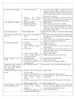
Page 37: ...Valve switch e Defective spark module f Gap too large between burner and electrode a Check power source b Replace spark electrode c Check connection between spark electrode and spark module d Check co...

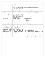
Page 38: ...uniform gas pressure 1 Check gas pressure Supply Regulator 2 Check orifice for blockage Metal shavings Dirt dust Excess grease from burner valve Floating flame lazy appearance and no well defined inn...

Page 39: ...39...

Page 40: ...40...

Page 41: ...41...

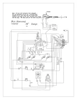
Page 42: ...42...

Page 43: ...43...

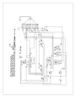
Page 44: ...44...

Page 45: ...45...

Page 46: ...46...

Page 47: ...onnection Exterior Plate Rail Control Panel Oven Door Kick Panel Voltage see pg 5 Oven Interior Porcelain Finish Oven Racks Ground see pg 5 Top Section Top Grates Ring Grates Burners Polarization see...

Reviews: