11.7.1 Powering up the modem
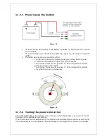
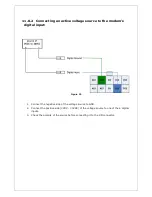
Figure 21
•
Connect the red wire directly to the battery’s positive (+) terminal or to a source
of 8-to-30Vdc
•
Connect the black wire directly to the battery’s negative (-) terminal or to ground
(GND)
•
The white wire must be connected to either:
o
The red wire to keep the modem powered on when there is power
o
A switch for manually turning on and off the modem
o
The vehicle’s “Accessory for position 2”, for turning ON the modem
without turning on the engine
o
The vehicle’s “Accessory for position 3”, for turning ON the modem
only when the engine is turned on.
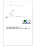
Figure 22
11.7.2 Testing the power connection
Check the PWR light on the modem: if it is turned on then the modem is powered. If it’s off,
then review the installation procedures.
If LED indicators are not accessible to the installer a personal computer can be used to verify
it’s functionality by running BlueVue Device Manager and attempt to connect to the modem.

