11.8 I/O Cable Wiring
The I/O specifications are available in the
Product Overview
section of this document.
It should be noted that the I/Os of the modem are not insulated. Caution must be used in
order to avoid causing damage to the modem and its attached peripherals.
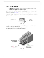
The 15-foot 10-pin I/O cable is available for purchase from BlueTree.
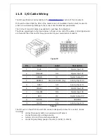
The Molex plug shown in the figure below is found at one end of the cable, and stripped wires
are found at the other end for easy connection to your equipment or sensors.
Pin
Color
Label
Description
1
BLUE
DI3
Digital Input #3
2
ORANGE
DI1
Digital Input #1
3
GREEN
O1
Digital Output #1
4
BROWN
AI3 (4600/5600 only)
Analog Input #3
5
GRAY
AI1
Analog Input #1
6
VIOLET
DI4
Digital Input #4
7
YELLOW
DI2
Digital Input #2
8
RED
O2
Digital Output #2
9
BLACK
GND
GROUND
10
WHITE
AI2
Analog Input #2
Table 11
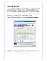
The I/O port on the BT-4000 and 5000 series is designed to allow for a variety of uses,
including:
•
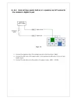
connecting a panic button or a passive on/off sensor
•
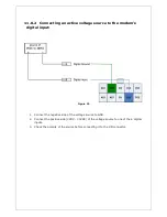
connecting an active voltage source
•
turning on and off an external peripheral
•
connecting an analog gauge or source (0-5Vdc) (4-20mA)
Figure 23

