background image

© BlueView Technologies Corp  

BlueView BV5000 User Handbook 

11 

  Chapter 3     System Assembly and Testing 


Assembling the Hardware 

1.


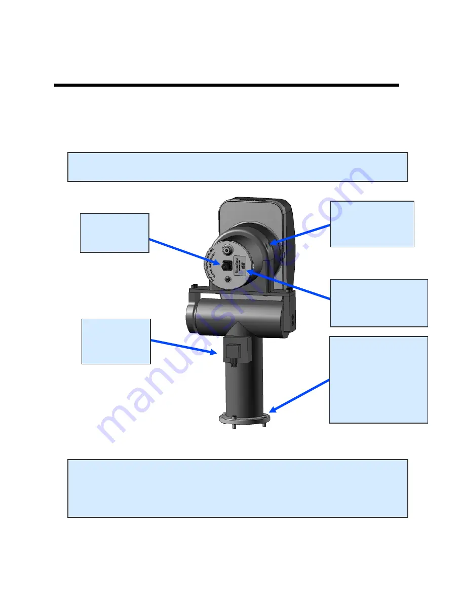
Attach the sonar into the sonar clamp by loosening the four cap screws, 
sliding in the sonar and retightening the four cap screws.  


NOTE: The sonar is inserted into the clamp such that its connector is on the same 

side as the Pan & Tilt connector.

NOTE

Use the stickers, side indicators, and connector placement on the 

rear end cap of the sonar to determine the up-down orientation of the sonar. 
If the sonar is inverted be sure to select the “inverted” option in ProScan’s 
settings. 

NOTE 

ORIENTATION OF 

SONAR 

2. SONAR 

CONNECTOR 

3. PAN & 

TILT 

CONNECTOR 

REFER TO THE 

PAN & TILT 

INSTALLATION 

SECTION FOR 

MOUNTING 

INSTRUCTIONS 

1. 4X CAP 

SCREWS FOR 

CLAMP 

Summary of Contents for BV5000

Page 1: ...www blueview com BV5000 User Handbook Part Number 202882 01 Revision A Updated April 2010 BlueView Technologies Inc All rights reserved All product names are trademarks of their respective companies ...

Page 2: ...and protected under U S and international copyright law Except as authorized under this License Agreement the Software may be used only on computers owned leased or otherwise controlled by you You may not reverse assemble reverse compile or otherwise translate ProScan Copyright 2003 2010 BlueView Technologies Corp All rights reserved No part of this publication may be copied reproduced or translat...

Page 3: ...ts 12 Installing the Pan and Tilt Drivers 13 Setup PC IP Address 16 Connect to the BV5000 17 Installation of the Pan Tilt Unit 18 Chapter 4 ProScan Software Basics 20 Typical ProScan Screenshot 20 Image Display 21 Toolbar 22 Toolbar 23 Range Controls 24 Range and Bearing 24 Playback Controls 25 Settings Sonar Control 26 Manual Image Calibration 27 Pan and Tilt Controls 28 Screen Information 29 Sca...

Page 4: ...37 Sonar Head Connection Issues 40 Image and Scan Problems 43 BlueView Customer Support 45 Chapter 7 System Specifications 46 Appendix A Typical Installation Configurations 47 Typical Tripod and Fixed Configurations 47 Typical ROV Configuration 48 Appendix B System and Cable Diagrams 49 Sonar Pan and Tilt Cable 49 Pan and Tilt Outline Drawing 50 MB2250 45 Outline Drawing 51 MB1350 45 Outline Drawi...

Page 5: ...nical scanning sonar system When ordered the BV5000 ships with either a 1 35 or 2 25 MHz sonar head which are both covered in this manual For specific details on individual sonar head specifications see the specifications tables listed in the specification section of this manual System Contents Verify that your delivered system includes the following components Sonar Head Pan Tilt Unit Sonar Pan T...

Page 6: ...pods and ROVs are shown in the figures below Notice the volumetric scan zones around the sonar With each scan a large amount of high resolution 3D data is collected The system works by mechanically scanning a thin vertical sonar slice around the selected area as shown in the figure below At each direction a profile of the surface is taken and added to the other direction profiles to create a final...

Page 7: ...er Scan Parameters and Start Scan Select the Scan button located under the pan and tilt controls to bring up the Scan Controls window Setup the desired scan process and enter any position and orientation data available not required Press Start Scan to begin the scan process Depending on how the scan is configured scans can take between 1 18 minutes to complete Monitor Scan Process ProScan visually...

Page 8: ...ed a warning message may pop up saying that ProScan is attempting to connect to the network BlueView recommends selecting the option that will always allow ProScan to access the network which it needs to do to communicate with sonar ProScan Software System Requirements ProScan requires a system that meets or exceeds the following requirements for optimum performance Windows 2000 XP or Vista operat...

Page 9: ...ard cad products BlueView sells the Cyclone package as an optional software accessory for those requiring this type of package Software Options Cyclone is originally installed with only its Viewer functionality enabled By purchasing additional licenses some of the more advanced features can be activated for use The table below outlines some of the different features associated with the different l...

Page 10: ... note of the installation directory 3 If you either requested a trial license or purchased a permanent license a license file should have been provided to you as a file named license dat 4 Copy this file into the installation directory 5 Launch Cyclone A dialog should appear outlining the available licenses and expiration dates 6 If the available licenses do not appear in the dialog the individual...

Page 11: ...ted into the clamp such that its connector is on the same side as the Pan Tilt connector NOTE Use the stickers side indicators and connector placement on the rear end cap of the sonar to determine the up down orientation of the sonar If the sonar is inverted be sure to select the inverted option in ProScan s settings NOTE ORIENTATION OF SONAR 2 SONAR CONNECTOR 3 PAN TILT CONNECTOR REFER TO THE PAN...

Page 12: ...st your system 1 Connect the sonar and Pan Tilt unit to the control box using the SPT Sonar Pan Tilt test cable Connect the Ethernet cable to the control box then to an available network connection port on the PC Verify that all connections in the diagram below have been made 2 Once all the connections are made connect the SPT Junction Box to an AC Power supply ...

Page 13: ...B port on the control box to an available USB port on the PC The Found New Hardware Wizard will guide you through the installation process 2 First the USB Serial Converter driver will install When prompted to use Windows Update to search for the driver select No not this time and click Next NOTE Two separate Found New Hardware Wizard windows will pop up Do not close the second install wizard while...

Page 14: ...all the driver from CD and click Next 4 Select Search for the best driver in these locations and check the box of Search removable media floppy CD ROM Then click on the Next button 5 When the driver is successfully installed the following window will pop up Click Finish to complete the installation of the first driver ...

Page 15: ...Windows Device Manager in Windows XP go to the Control Panel Æ Performance and Maintenance Æ System click the Hardware tab then the Device Manager button Take note of the COM port number assigned to the USB COM port To access the Windows Device Manager click Start then RIGHT CLICK on my computer in the start menu and select Manage Click on Device Manager in the left panel Expand Ports COM and LPT ...

Page 16: ...col TCP IP in the list of components Make sure the IP address is set as shown below Windows Vista To access a PC s IP address in Windows Vista click Start Æ Control Panel Æ Network and Internet Æ Network and Sharing Center Æ Manage network connections Right click the connection that should be changed and click Properties You may be asked for an administrator password Click the Networking tab Under...

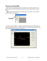
Page 17: ... ProScan Software and click on the connect button as shown below Note that if the sonar has just received power it will take 30 sec to boot and be ready for a connection When the connect button is pressed ProScan should connect automatically to the sonar and the pan tilt If ProScan does not find the sonar or pan tilt look at the troubleshooting section of this manual Connect ...

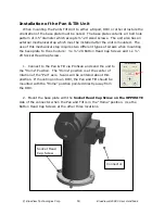
Page 18: ...hanical stop requires two different types of screws when mounting the base plate to the structure 3 x 20 Button Head Cap Screws and 1 x 20 Socket Head Cap Screw 1 Connect to the Pan Tilt via ProScan and send the unit to the Home Position The Home position is at the center of rotation of the Pan axis Scans will be centered about this position If mounting onto an ROV the Pan and Tilt should be mount...

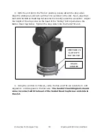
Page 19: ...at bolt with the Button Head Cap Screw which is directly under the connector Adjust the height of the stop collar so the head of the sliding bolt is just above the Button Head Cap Screw Tighten the stop collar onto the Pan Tilt unit 4 Using the controls in ProScan verify the Pan and Tilt can rotate from 180 degrees to 180 degrees in the Pan axis The head of the sliding bolt should come in contact ...

Page 20: ...etting up and running a 3D scan operation While ProScan can output 3D point cloud files in several formats it does not work directly with 3D data sets For viewing and manipulation of 3D data see the following chapters regarding working with point clouds Typical ProScan Screenshot Toolbar Range Controls Range and Bearing Pan and Tilt Controls Image Display ...

Page 21: ...p of the intensity map is the range value chosen for each angle for use in the creation of 3D point clouds This range data shows up in blue The range data is chosen using a threshold routine and the threshold value set in the File Settings Sonar Controls window If no data in a given angle bin meets the threshold requirement no blue is shown and no point is assigned in the point cloud for that angl...

Page 22: ...is displayed in ProScan The following diagrams illustrate how to interpret the image display as well as how the line data translates to the point cloud Clockwise from upper left Illustration of the multibeam collection display of the line data in the copper color map display of the blue threshold data points display of the point cloud ...

Page 23: ...matically Network Transmit This function is not used with the BV5000 setup New File This function is not used with the BV5000 setup Automatic Image Calibration This will perform an automatic Image Calibration To calibrate the image first make sure that the sonar is thermally stabilized to the ambient water temperature then click the icon A dialog box will be displayed to provide an example of the ...

Page 24: ...lear the measurement line press the Measurement button a second time or right click the mouse Range Controls The sonar range sliders along the left side of the ProScan window allow you to change both the start and stop range both are measured in meters The stop range selects how far out the sonar is looking whereas the start range selects where the sonar starts acquiring data By using both control...

Page 25: ...vailable Also available between the previous ping and next ping buttons is the time slider It shows the current location inside the file You may click on it to jump to a new location or simply drag the marker back and forth to quickly scan through a file Function Icon Description Pause Pause playback at the current ping Play Resume playback Previous Ping Go to the previous ping Next Ping Go to the...

Page 26: ...ngs tab is discussed later in this manual Range Threshold Level controls The Range Threshold controls the value at which a target will be recognized The allowed values range from 100 to 20 000 The default value is 250 and values typically range from 100 to 500 Sound Velocity This is the sound velocity in meters per second used to compute target range Override recorded Sound Velocity To replace the...

Page 27: ...hronize the imagery between them To calibrate the image first make sure that the sonar is thermally stabilized to the ambient water temperature then use the pan and tilt controls to point the sonar so that its beam is grazing a relatively flat surface such as a piling or the seafloor and displaying a diagonal line across the image display If the diagonal line has a break in it as shown in the left...

Page 28: ...buttons to move the pan and tilt Home Position The Pan Tilt Home position is defined as the center rotation angle for each axis To move to the Home position click the corresponding button Start Scan Rotational scans are performed by clicking the Start Scan button on the Pan Tilt control panel or by clicking File Æ Start Scan Both Single Scans and Spherical Scans can be performed from the Scan Setu...

Page 29: ...in the background to create high resolution 3D point clouds The ping rate display represents the rate that ProScan is collecting data in the background Time Stamp This is the time stamp for the current ping image Sonar Type This message lets you know if you are looking at live or saved data It also gives you information regarding which sonar created the current sonar data Sound Speed This message ...

Page 30: ... Scan Settings Running Single Scans The term single scan refers to a scan collected at a single tilt angle To run a single scan first move the sonar to the desired tilt angle then check the Single Scan box set the desired Scan Speed and Total Pan Angle and click Start Scan A progress window will appear while the scan is running Running Spherical Scans Spherical scans allow a greater volume to be s...

Page 31: ...ans can both be set to a specific sector size There are many situations when scans less than 360 degrees are adequate speeding up the scan process significantly These controls allow you to set the total pan angle for the upcoming scan Scan Speed Adjusting the scan speed allows the user to sacrifice point cloud density for faster scan rates This setting is adjustable between 1 and 10 degrees per se...

Page 32: ...rols When conducting Spherical Scans the combined Merged File Name can be assigned in the Scan Setup dialog box This file name overrides the default name Position and Orientation Input If the orientation and position of the BV5000 unit are known that data can be entered in the Scan Setup dialog box The exported point could files are adjusted such that the Z axis normal to the earth s surface and t...

Page 33: ...ection describes these items in detail Configure Recording Click File Æ Settings Æ Recording tab to bring up the File Recording Setup dialog To enable data logging check File Recording Enabled and press OK To change where files are saved type in a new location or click Browse to select one Checking the Save Individual Scan Files box in the Scan Settings tab will preserve the files generated for ea...

Page 34: ...descried above SON files are automatically created during scans 3D Point Cloud files are also created automatically with the same names as the SON file Two kinds of 3D Point Cloud files are created XYZ files with the extension xyz and OFF files with the extension off Both kinds of 3D Point Cloud files are in ASCII format and represent 3D points using X Y and Z coordinates The X and Y values are in...

Page 35: ... speed calibration setting TVG gain sonar type threshold setting physical offsets and the comments field Reviewing Data When Meshlab is installed and the Run Meshlab after each scan box is checked File Æ Settings Æ Recording tab the OFF file is opened and the 3D point cloud file can be reviewed Reprocessing Saved Data As previously noted one of the unique aspects of the BV5000 system is the abilit...

Page 36: ...ck control bar This will bring up a Playback Scan Setup window This window allows adjusting the position and orientation inputs used during reprocessing Once you have made any desired changes to this section press the Start Playback button to start the reprocessing procedure Once complete ProScan creates new versions of the xyz and msh files The raw son file is left untouched If MeshLab is install...

Page 37: ... own connector and conductor sets for communications all the way back to the computer This can help isolated problems quickly since the only items shared are the DC power supply DC power lines and SPT Cable Try running through the individual troubleshooting components described further in this chapter Pan Tilt Connection Issues Connect with Test Cable Change USB Ports Verify USB Com Port Reinstall...

Page 38: ... If you were not able to connect to the pan and tilt go on to the next section Verify USB Com Port Verify USB Com Port The pan and tilt connects to the PC through a USB to RS485 converter located in the SPT box When the USB connection is made and all the drivers are installed properly this connection will show up in the Device Manager Ports Com and LPT as a USB Com Port If you do not see the USB C...

Page 39: ...onnectors It is not uncommon for topside connectors to get pulled out of their ports or subsea connectors to get corroded Power down the system and check the condition and proper seating of all connectors in the system If you were not able to connect to the sonar go on to the next section Check Power Check Power If the sonar does not receive the correct DC voltage on the correct pins it can not op...

Page 40: ...ick File Settings Sonar Connection to display the Sonar Connection Options The sonar s default network address is shown below The Head Number for BlueView s MicroBathymetry MB series sonar will be zero The head number for non MB sonar will be zero or one Reboot PC and Sonar Power down both the sonar and computer wait 10 seconds then power everything up This can solve network configuration problems...

Page 41: ...nar and check the condition and proper seating of all connectors in the system Once you have verified condition and proper seating of all connectors re power the Sonar wait 35 seconds then try to reconnect to the sonar from ProScan software If you were not able to connect to the sonar go on to the next section Check Power Check Power If the sonar does not receive the correct DC voltage on the corr...

Page 42: ...worth taking a quick second to verify that the sonar is working properly This is accomplished by setting up a bench top test using the test cables and AC power supply that came with the sonar This test will quickly tell us whether the problem is with the sonar PC or with the rest of the system Use the following instructions to setup and test your sonar Refer to section Connect Components in this m...

Page 43: ...ation section of this manual Spherical Scan process stopped before final point cloud creation During a spherical scan process the data for each horizontal sweep is stored in a separate temporary file When all horizontal scans are completed the individual scans are combined into a single file If the system shuts down or aborts before the software reaches the merge portion of the process the operato...

Page 44: ...vert Beam Angles checkbox and click the Save button For post processing 3 Open the rotational scan file and perform a playback scan see the ProScan manual for more details 4 When playback is complete new and corrected XYZ and OFF files will be created in the directory of the SON file Sonar is not mounted vertical in Pan Tilt mount As the system scans a scene the software assumes the sonar is mount...

Page 45: ...improve image quality it may be that the scan speed is too high This can be changed in the Scan Setup window See the ProScan manual for more information BlueView Customer Support At this point if you were able to connect to your BV 500 you can assume the system is working properly and that the PC is set up correctly The only thing left is the communications link specific to your particular impleme...

Page 46: ...in Air 21 7 lbs 19 1 lbs Weight in Water 8 2 lbs 6 0 lbs Depth Rating 300 m 1 000 ft 300 m 1 000 ft Electrical Power Consumption 45 W 45 W SPT Junction Box 120 240 VDC 120 240 VDC Voltage Directly to Head if SPT box not used 12 48 VDC 12 48 VDC Voltage Directly to Pan Tilt if SPT box not used 20 29 VDC 20 29 VDC Communications Required Com Channels Ethernet and RS485 Ethernet and RS485 Ethernet Ba...

Page 47: ... BlueView Technologies Corp BlueView BV5000 User Handbook 47 Appendix A Typical Installation Configurations Typical Tripod and Fixed Configurations ...

Page 48: ... Ethernet connection first Then try a crossed connection swap 1 3 2 6 Function RJ45 Pins Ethernet Rx 1 Ethernet Rx 2 Ethernet Tx 3 Ethernet Tx 6 Ethernet to Fiber Converter Sonar Pan Tilt RS485 BlueView Supplied Whip Sonar to Customer Whip Function Pin Whip Cable Color 12 48 VDC 4 Blue and Blue White Ground 7 Brown and Brown White Ethernet Rx 1 Orange White Ethernet Rx 2 Orange Ethernet Tx 3 Green...

Page 49: ...sonar 3 Ethernet TX to sonar 4 24V DC 5 24V DC 6 Ethernet TX to sonar 7 Ground 8 Ground 9 N C 10 N C 4 Pin Connector to Pan Tilt Unit Impulse LPMIL 4 FS Pin Function 1 DC Common 2 24V DC 3 Data B 4 Data A 8 Pin Connector to Sonar and Pan Tilt Unit Souriau UTG612 8PN Pin Function A Ethernet RX to sonar B Ethernet RX to sonar C Ethernet TX to sonar D 24V DC E 24 DC Common F Ethernet TX to sonar G Da...

Page 50: ... BlueView Technologies Corp BlueView BV5000 User Handbook 50 Pan and Tilt Outline Drawing Units Inches ...

Page 51: ... BlueView Technologies Corp BlueView BV5000 User Handbook 51 MB2250 45 Outline Drawing Units Inches ...

Page 52: ... BlueView Technologies Corp BlueView BV5000 User Handbook 52 MB1350 45 Outline Drawing Units Inches ...

Reviews: