background image

- 7 -


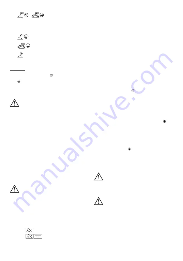
WELDING MACHINE WITH THREE-POSITION SWITCH:


• 

 - 


MMA electrode welding

    The choice between the two positions in MMA is made 

according to the type of electrode used.


  A special device, the Arc Control System, guarantees improved 

welding dynamics, easy starting (HO START) and fluid welding 

(ARC FORCE) with each type of electrode:


  Rutile,  stainless  steel  and  other  types  of 

electrode.


  Basic, aluminium, cellulose (mod. CE), and other 

types of electrode.


• 


TIG welding with scratch strike:


  ANTI STICK device specific for TIG.


  (HOT START and ARC FORCE not enabled).

on the back:

Fig. D

1-   Power  supply  cable,  2p  + 

 (1~), with EEC plug where 

required; the power supply cable for the three-phase model is 3p 

 (3~).


(The cable of the “DUAL VOLTAGE AUTOMATIC” model does 

not have a plug).

2-   Main Switch O/OFF - I/ON (lit where required).

5. INSTALLATION

WARNING!  CARRY  OUT  ALL  INSTALLATION 

OPERATIONS  AND  ELECTRICAL  CONNECTIONS  WITH  THE 

WELDING  MACHINE  COMPLETELY  SWITCHED  OFF  AND 

DISCONNECTED FROM THE POWER SUPPLY OUTLET.

THE ELECTRICAL CONNECTIONS MUST BE MADE ONLY AND 

EXCLUSIVELY BY AUTHORISED OR QUALIFIED PERSONNEL.

PREPARATION

Unpack the welding machine, assemble the separate parts contained 

in the package.

Assembling the return cable-clamp

Fig. E

Assembling the welding cable-electrode holder clamp

Fig. F

HOW TO LIFT THE WELDING MACHINE

All the welding machines described in this handbook should be lifted 

using the handle or strap supplied if provided for the particular model.

POSITION OF THE WELDING MACHINE

Choose the place to install the welding machine so that the cooling 

air  inlets  and  outlets  are  not  obstructed  (forced  circulation  by  fan, 

if present); at the same time make sure that conductive dusts, 

corrosive vapours, humidity etc. will not be sucked into the machine.

Leave at least 250mm free space around the welding machine.

WARNING!  Position  the  welding  machine  on  a  flat 

surface  with  sufficient  carrying  capacity  for  its  weight,  to 

prevent it from tipping or moving hazardously.

CONNECTION TO THE MAIN POWER SUPPLY

-  Before  making  any  electrical  connection,  make  sure  the  rating 

data of the welding machine correspond to the mains voltage and 

frequency available at the place of installation.

-  The welding machine should only be connected to a power supply 

system with the neutral conductor connected to earth.

-  To ensure protection against indirect contact use residual current 

devices of the following types:

  -  Type A ( 

 ) for single phase machines;

  -  Type B ( 

 ) for 3-phase machines.

-  In order to satisfy the requirements of the EN 61000-3-11 (Flicker) 

standard we recommend connecting the welding machine to the 

interface points of the main power supply that have an impedance 

of less than:

  For model 1~

  Zmax = 0.221 Ohm (160A, 180A).

  Zmax = 0.170 Ohm (200A).

  -  the welding machine does not fall within the requisites of IEC/EN 

61000-3-12 standard.

    Should  it  be  connected  to  a  public  mains  system,  it  is  the 

installer’s responsibility to verify that the welding machine itself is 

suitable for connecting to it (if necessary, consult the distribution 

network company).

  For model 3~

  Zmax = 0.283 Ohm. 

  -  the welding machine does not fall within the requisites of IEC/EN 

61000-3-12 standard.

    Should  it  be  connected  to  a  public  mains  system,  it  is  the 

installer’s responsibility to verify that the welding machine itself is 

suitable for connecting to it (if necessary, consult the distribution 

network company).

-  Unless  otherwise  specified  (MPGE),  the  welding  machines  are 

compatible with power generating sets for voltage oscillations up 

to ± 15%.

  For correct use, the power generating set must be brought to 

steady conditions before being able to connect the inverter.

-  PLUG AND OUTLET:


-  The 230V model

 is fitted at the factory with a power supply cable 

and normalised plug, (2P + 

) 16A/250V.

    It can therefore be connected to a mains outlet fitted with fuses 

or an automatic circuit-breaker; the special earth terminal should 

be connected to the earth conductor (yellow-green) of the power 

supply line.

  Table 

(TAB.1)

  shows  the  recommended  delayed  fuse  sizes  in 

amps, chosen according to the max. nominal current supplied by 

the welding machine, and the nominal voltage of the main power 

supply.


- For welding machines without a plug (115/230V models) 

/ (230V models)

, connect a normalised plug (2P + 

 (1~)) 

- having sufficient capacity- to the power  cable and prepare  a 

mains  outlet  fitted  with  fuses  or  an  automatic  circuit-breaker; 

the special earth terminal should be connected to the earth 

conductor (yellow-green) of the power supply line. Table 

(TAB.1)


shows  the  recommended  delayed  fuse  sizes  in  amps,  chosen 

according to the max. nominal current supplied by the welding 

machine, and the nominal voltage of the main power supply.


-  For welding machines without a plug (400V models)

, connect 

a normalised plug (3P + 

 (3~)) - having sufficient capacity- to 

the power cable and prepare a mains outlet fitted with fuses or 

an automatic circuit-breaker; the special earth terminal should 

be connected to the earth conductor (yellow-green) of the power 

supply line. Table 

(TAB.1)

 shows the recommended delayed fuse 

sizes in amps, chosen according to the max. nominal current 

supplied by the welding machine, and the nominal voltage of the 

main power supply.


WARNING!  Failure  to  observe  the  above  rules  will 

make the (Class 1) safety system installed by the manufacturer 

ineffective  with  consequent  serious  risks  to  persons  (e.g. 

electric shock) and objects (e.g. fire).

CONNECTION OF THE WELDING CABLES

WARNING!  BEFORE  MAKING  THE  FOLLOWING 

CONNECTIONS  MAKE  SURE  THE  WELDING  MACHINE  IS 

SWITCHED  OFF  AND  DISCONNECTED  FROM  THE  POWER 

SUPPLY OUTLET.

Table

 (TAB.1) 

gives the recommended values for the welding cables 

(in mm

2

) depending on the maximum current supplied by the welding 

machine.

MMA WELDING

Almost all coated electrodes are connected to the positive pole (+) 

of the power source; as an exception to the negative pole (-) for acid 

coated electrodes.

WELDING OPERATIONS WITH DIRECT CURRENT

Connecting the electrode-holder clamp welding cable

Summary of Contents for Active 187

Page 1: ...EDAMPE N FARE FOR SVEISERØYK SF HITSAUSSAVUJEN VAARA CZ NEBEZPEČÍ SVAŘOVACÍCH DÝMŮ SK NEBEZPEČENSTVO VÝPAROV ZO ZVÁRANIA SI NEVARNOST VARILNEGA DIMA HR SCG OPASNOST OD DIMA PRILIKOM VARENJA LT SUVIRINIMO DŪMŲ PAVOJUS EE KEEVITAMISEL SUITSU OHT LV METINĀŠANAS IZTVAIKOJUMU BĪSTAMĪBA BG ОПАСНОСТ ОТ ПУШЕКА ПРИ ЗАВАРЯВАНЕ PL NIEBEZPIECZEŃSTWO OPARÓW SPAWALNICZYCH GB DANGER OF EXPLOSION I PERICOLO ESPLO...

Page 2: ...GRO GENÉRICO D GEFAHR ALLGEMEINER ART RU ОБЩАЯ ОПАСНОСТЬ P PERIGO GERAL GR ΓΕΝΙΚΟΣ ΚΙΝΔΥΝΟΣ NL ALGEMEEN GEVAAR H ÁLTALÁNOS VESZÉLY RO PERICOL GENERAL S ALLMÄN FARA DK ALMEN FARE N GENERISK FARE STRÅLNING SF YLEINEN VAARA CZ VŠEOBECNÉ NEBEZPEČÍ SK VŠEOBECNÉ NEBEZPEČENSTVO SI SPLOŠNA NEVARNOST HR SCG OPĆA OPASNOST LT BENDRAS PAVOJUS EE ÜLDINE OHT LV VISPĀRĪGA BĪSTAMĪBA BG ОБЩИ ОПАСТНОСТИ PL OGÓLNE N...

Page 3: ...TES ATT ANVÄNDA MASKINEN DK DET ER FORBUDT FOR PERSONER MED METALPROTESER AT BENYTTE MASKINEN N BRUK AV MASKINEN ER IKKE TILLATT FOR PERSONER MED METALLPROTESER SF KONEEN KÄYTTÖ KIELLETTY METALLIPROTEESIEN KANTAJILTA CZ ZÁKAZ POUŽITÍ STROJE NOSITELŮM KOVOVÝCH PROTÉZ SK ZÁKAZ POUŽITIA STROJA OSOBÁM S KOVOVÝMI PROTÉZAMI SI PREPOVEDANA UPORABA STROJA ZA NOSILCE KOVINSKIH PROTEZ HR SCG ZABRANJENA UPOT...

Page 4: ...psortering av elektriska och elektroniska apparater Användaren får inte sortera denna anordning tillsammans med blandat fast hushållsavfall utan måste vända sig till en auktoriserad insamlingsstation DK Symbol der står for særlig indsamling af elektriske og elektroniske apparater Brugeren har pligt til ikke at bortskaffe dette apparat som blandet fast byaffald der skal rettes henvendelse til et au...

Page 5: ...heses etc Adequate protective measures must be adopted for persons with these types of medical apparatus For example they must be forbidden access to the area in which welding machines are in operation This welding machine conforms to technical product standards for exclusive use in an industrial environment for professional purposes It does not assure compliance with the basic limits relative to ...

Page 6: ...CRIPTION OF THE WELDING MACHINE The unit is comprised of power modules which have been developed on a specially printed circuit designed to maximise reliability and reduce maintainance Fig B 1 Power supply input 1 3 rectifier group and balancing capacitors 2 Transistors and drivers switching bridge IGBT It turns the mains rectified voltage into high frequency alternate voltage and permits power re...

Page 7: ... the installer s responsibility to verify that the welding machine itself is suitable for connecting to it if necessary consult the distribution network company For model 3 Zmax 0 283 Ohm the welding machine does not fall within the requisites of IEC EN 61000 3 12 standard Should it be connected to a public mains system it is the installer s responsibility to verify that the welding machine itself...

Page 8: ...HINE IS SWITCHED OFF AND DISCONNECTED FROM THE MAIN POWER SUPPLY EXTRAORDINARY MAINTENANCE EXTRAORDINARY MAINTENANCE MUST ONLY BE CARRIED OUT BY TECHNICIANS WHO ARE EXPERT OR QUALIFIED IN THE ELECTRIC MECHANICAL FIELD AND IN FULL RESPECT OF THE IEC EN 60974 4 TECHNICAL DIRECTIVE WARNING BEFORE REMOVING THE WELDING MACHINE PANELS AND WORKING INSIDE THE MACHINE MAKE SURE THE WELDING MACHINE IS SWITC...

Page 9: ...di campi elettromagnetici EMF localizzati nei dintorni del circuito di saldatura I campi elettromagnetici possono interferire con alcune apparecchiature mediche es Pace maker respiratori protesi metalliche etc Devono essere prese adeguate misure protettive nei confronti dei portatori di queste apparecchiature Ad esempio proibire l accesso all area di utilizzo della saldatrice Questa saldatrice sod...

Page 10: ...vedi tabella 2 TAB 2 Il peso della saldatrice è riportato in tabella 1 TAB 1 4 DESCRIZIONE DELLA SALDATRICE La saldatrice è costituita essenzialmente da moduli di potenza realizzati su circuiti stampati ed ottimizzati per ottenere massima affidabilità e ridotta manutenzione Fig B 1 Ingresso linea di alimentazione 1 3 gruppo raddrizzatore e condensatori di livellamento 2 Ponte switching a transisto...

Page 11: ...imentazione che presentano un impedenza minore di Per modello 1 Zmax 0 221 Ohm 160A 180A Zmax 0 170 Ohm 200A La saldatrice non rientra nei requisiti della norma IEC EN 61000 3 12 Se essa viene collegata a una rete di alimentazione pubblica è responsabilità dell installatore o dell utilizzatore verificare che la saldatrice possa essere connessa se necessario consultare il gestore della rete di dist...

Page 12: ...ettrodo dal bagno di fusione per ottenere lo spegnimento dell arco ASPETTI DEL CORDONE DI SALDATURA Fig H 7 MANUTENZIONE ATTENZIONE PRIMA DI ESEGUIRE LE OPERAZIONI DI MANUTENZIONE ACCERTARSI CHE LA SALDATRICE SIA SPENTA E SCOLLEGATA DALLA RETE DI ALIMENTAZIONE MANUTENZIONE STRAORDINARIA LE OPERAZIONI DI MANUTENZIONE STRAORDINARIA DEVONO ESSERE ESEGUITE ESCLUSIVAMENTE DA PERSONALE ESPERTO O QUALIFI...

Page 13: ...iderme aux rayons ultraviolets produits par l arc Ces mesures de protection doivent également être étendues à toute personne se trouvant à proximité de l arc au moyen d écrans ou de rideaux non réfléchissants Le passage du courant de soudage génère des champs électromagnétiques EMF localisés aux alentours du circuit de soudage Ces champs électromagnétiques risquent de créer des interférences avec ...

Page 14: ... se référant aux normes de sécurité dont la signification figure au chapitre 1 Règles générales de sécurité pour le soudage à l arc Note La plaquette représentée indique la signification des symboles et des chiffres les valeurs exactes des informations techniques du poste de soudage doivent être vérifiées directement sur la plaquette du poste de soudage AUTRES INFORMATIONS TECHNIQUES POSTE DE SOUD...

Page 15: ...courroie fournie POSITIONNEMENT DU POSTE DE SOUDURE Choisir un lieu d installation ne comportant aucun obstacle face à l ouverture d entrée et de sortie de l air de refroidissement circulation forcée par ventilateur si prévu s assurer qu aucune poussière conductrice vapeur corrosive humidité etc n est aspirée Laisser un espace dégagé minimum de 250mm autour de la machine ATTENTION Installer le pos...

Page 16: ...latif Le courant de soudage se règle en fonction du diamètre de l électrode utilisée et du type de joint que l on désire effectuer à titre indicatif les courants utilisables pour les différentes diamètres d électrodes sont Ø Électrode mm Courant de soudage A min max 1 6 25 50 2 40 80 2 5 60 110 3 2 80 160 4 120 200 5 180 260 Il ne faut pas oublier que à diamètre d électrode égal des valeurs élevée...

Page 17: ... los elementos desgastados del soplete Hacer la instalación eléctrica respetando las normas y leyes de prevención de accidentes previstas La soldadora debe conectarse exclusivamente a un sistema de alimentación con conductor de neutro conectado a tierra Asegurarse de que la toma de corriente esté correctamente conectada a la tierra de protección No utilizar la soldadora en ambientes húmedos o moja...

Page 18: ...o 5 Símbolo de la estructura interna de la soldadora 6 Norma EUROPEA de referencia para la seguridad y la fabricación de las máquinas para soldadura por arco 7 Número de matrícula para la identificación de la soldadora indispensable para la asistencia técnica solicitud de recambio búsqueda del origen del producto 8 Prestaciones del circuito de soldadura U0 tensión máxima en vacío I2 U2 Corriente y...

Page 19: ...realiza en función del tipo de electrodo utilizado Un dispositivo especial el Arc Control System garantiza la mejor dinámica de soldadura un arranque fácil HOT START una soldadura fluida ARC FORCE para cada tipología de electrodo Electrodos con revestimientos de rutilo inoxidables etc Electrodos básicos de aluminio celulósicos modelo CE etc Soldadura TIG con cebado por roce Dispositivo ANTISTICK e...

Page 20: ...orriente de soldadura Se conecta a la pieza a soldar o al banco metálico en el que se apoya lo más cerca posible de la junta en ejecución Este cable se conecta al borne con el símbolo Recomendaciones Girar a fondo los conectores de los cables de soldadura en las tomas rápidas si están presentes para garantizar un contacto eléctrico perfecto en caso contrario se producirán sobrecalentamientos de lo...

Page 21: ...tal caso proceda a la eliminación de este inconveniente Las conexiones del circuito de soldadura se efectúan correctamente particularmente que la pinza del cable de masa esté efectivamente conectada a la pieza y sin interposición de materiales aislantes Ej Barnices El gas de protección usado sea correcto Argón 99 5 y en la justa cantidad D BEDIENUNGSANLEITUNG ACHTUNG VOR GEBRAUCH DER SCHWEISSMASCH...

Page 22: ...hinen an einem einzigen Werkstück oder an mehreren elektrisch miteinander verbundenen Werkstücken gearbeitet können sich die Leerlaufspannungen zwischen zwei verschiedenen Elektrodenklemmen oder Brennern gefährlich aufsummieren bis hin zum Doppelten des zulässigen Grenzwertes Ein Fachkoordinator hat eine Instrumentenmessung vorzunehmen um festzustellen ob ein Risiko besteht und ob die angemessenen...

Page 23: ...oder mit 230V ac gespeist wird Abb C 3 Die GRÜNE LED weist darauf hin daß das Gerät an das Netz mit 230V ac angeschlossen ist Die ORANGEFARBENE LED bedeutet daß das Gerät an das Netz mit 115V ac angeschlossen ist Während des Betriebes im 115V ac Modus kommt es vor daß bei längeren und stärkeren Überspannungen das Gerät in den 230V ac Betrieb umschaltet In diesem Fall muß das Gerät zur Wiederaufnah...

Page 24: ...zdose mit Sicherungen oder Leistungsschalter verbunden werden Der zugehörige Erdungsanschluß muß mit dem Schutzleiter gelb grün der Versorgungsleitung verbunden werden In Tabelle TAB 1 sind die empfohlenen Amperewerte der trägen Leitungssicherungen aufgeführt die auszuwählen sind nach dem von der Schweißmaschine abgegebenen max Nennstrom und der Versorgungsnennspannung Für Schweißmaschinen ohne St...

Page 25: ...it spannungsführenden Teilen oder von Verletzungen beim direkten Kontakt mit Bewegungselementen Regelmäßig und in der Häufigkeit auf die Verwendungsweise und die Staubentwicklung am Arbeitsort abgestimmt muß das Innere der Schweißmaschine inspiziert werden Der Staub der sich auf Transformator Reaktanz und Gleichrichter abgelagert hat ist mit trockener Druckluft abzublasen max 10bar Vermeiden Sie e...

Page 26: ...платформ или ковров Всегда защищать глаза специальными неактиничными стеклами монтированными на маски и на каски Пользоваться защитной невозгораемой спецодеждой избегая подвергать кожу воздействию ультрафиолетовых и инфракрасных лучей производимых дугой защита должна относиться также к прочим лицам находящимся поблизости от дуги при помощи экранов или не отражающих штор Прохождение сварочного тока...

Page 27: ...ксимальный ток потребляемый от сети I1 еff эффективный ток потребляемый от сети 10 Величина плавких предохранителей замедленного действия предусматриваемых для защиты линии 11 Символы соответствующие правилам безопасности чье значение приведено в главе 1 Общая техника безопасности для дуговой сварки Примечание Пример идентификационной таблички является указательным для объяснения значения символов...

Page 28: ...3p п 3 Модель DUAL VOLTAGE AUTOMATIC поставляется с кабелем без вилки 2 Главный выключатель O OFF I ON загорается индикатор если он предусмотрен 5 УСТАНОВКА ВНИМАНИЕ ВЫПОЛНИТЬ ВСЕ ОПЕРАЦИИ ПО УСТАНОВКЕ И ЭЛЕКТРИЧЕСКОЕ СОЕДИНЕНИЕ СО СВАРОЧНЫМ АППАРАТОМ ОТКЛЮЧЕННЫМ И ОТСОЕДИНЕННЫМ ОТ СЕТИ ПИТАНИЯ ЭЛЕКТРИЧЕСКИЕ СОЕДИНЕНИЯ ДОЛЖНЫ ВЫПОЛНЯТЬСЯ ТОЛЬКО ОПЫТНЫМ И КВАЛИФИЦИРОВАННЫМ ПЕРСОНАЛОМ СБОРКА Снять с...

Page 29: ... зажим который нужен для закручивания открытой части электрода Этот кабель необходимо соединить с зажимом обозначенным символом Соединение кабеля возврата тока сварки Соединяется со свариваемой деталью или с металлическим столом на котором она лежит как можно ближе к выполняемому сварному соединению Этот кабель необходимо соединить с зажимом обозначенным символом Рекомендации Закрутить до конца со...

Page 30: ...пряжения были бы должным образом отделены от соединений вторичной обмотки низкого напряжения Для закрытия металлоконструкции установите обратно все гайки и винты 8 ПОИСК НЕИСПРАВНОСТЕЙ В случаях неудовлетворительной работы аппарата перед ПРОВЕДЕНИЕМ СИСТЕМАТИЧЕСКОЙ ПРОВЕРКИ И обращением в сервисный центр проверьте следующее Убедиться что ток сварки величина которого регулируется потенциометром со ...

Page 31: ... 104 FIG A FIG B FIG C A V A V 6 4 5 9 8 7 FUSE T A 11 10 5 1 2 3 4 POWER MODULE CONTROL MODULE 115V 230V 400V 50 60Hz 4 4 5 5 2 3 3 2 1 1 6 ...

Page 32: ... 105 FIG D 2 1 2 1 FIG E FIG F 2 1 ...

Page 33: ...E CORRECTA GR SWSTO KORDONI NL JUISTE LASSTROOM H A ZÁRÓVONAL PONTOS RO CORDON DE SUDURĂ CORECT S RÄTT STRÖM DK KORREKT STRØMSTYRKE N RIKTIG STRØM SF VIRTA OIKEA CZ SPRÁVNÝ SVAR SK SPRÁVNY ZVAR SI PRAVILEN ZVAR HR SCG ISPRAVLJENI KABEL LT TAISYKLINGA SIŪLĖ EE KORREKTNE NÖÖR LV PAREIZA ŠUVE BG ПРАВИЛЕН ШЕВ PL PRAWIDłOWY ŚCIEG GB ADVANCEMENT TOO FAST I AVANZAMENTO TROPPO VELOCE F AVANCEMENT EXCESSIF...

Page 34: ...AL DATA DATI TECNICI PINZA PORTAELETTRODO I2 max 115V 230V 115V 230V mm2 kg 160A T20A 32A 25 4 8 180A T20A 32A 25 4 8 180A T25A 32A 25 6 1 200A T25A 32A 25 6 1 I2 max 115V 400V 115V 400V mm2 kg 220A T10A 16A 16 5 8 VOLTAGE CLASS 113V I2 max A I max A X ø mm ø mm2 80 130 200 150 35 60 2 4 10 150 220 16 25 ...

Reviews: