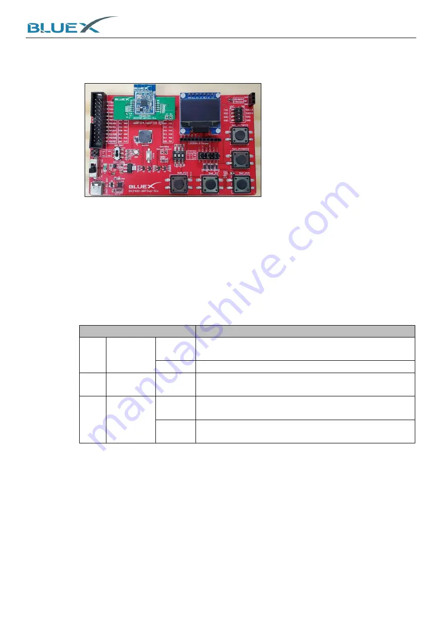
System Installation of Evaluation Kit
4
(6)
Module Adapter Board
A.
When BX2416/ RF03/ RF04/ RF08 modules welded on adapter board, plug in here on the
EVK as below:
(7)
RF04/ RF08 Module Welded Area
A.
RF04/ RF08 Module can be welded here on the EVK.
(8)
Buzzer
(9)
Secondary Power Switch
Please refer to #2, primary power switch, for comparison.
(10)
RGB LED
(11)
RF0x Module Reset Button
A.
Press this button to reset chip on module.
(12)
OLED Display Screen
(13)
LIS3DSH Acceleration Transducer Connector
(14)
P16/ P23/ Watchdog DIP Switch
#14 Switch
Description
Left
P16
Up
BOOT Pin of chip. Chip activated from UART0 P12(TX)/
P13(RX) for firmware download.
Down
Chip activated from Flash.
Mid
P23
Down
When using chips RF08 on module, switch this down
before power-on.
Right
Watchdog
Up
Watchdog timeout period is around 25sec, and module
will reset afterwards.
Down
Switch down when no using it. If there's no Watchdog IC
welded on EVK, no need to concern this switch.
(15)
Circuit Connector (P10/ P11/ P21)
A.
P10 for RGB LED green, or DC pin from OLED display screen.
B.
P11 for RGB LED blue, or RST pin from OLED display screen.
C.
P21 for RGB LED red, or QD pin from humidity sensors.
(16)
DS18B20 Humidity Sensors Connector
(17)
UART Connector
A.
Connect to RF0x UART P12/ P13 connector.
(18)
SWD Connector
A.
J-Link SWD debugging connector for RF0x module programming and softeare debugging.
Summary of Contents for BX2400-dRF0xp-S1c
Page 15: ...System Installation of Evaluation Kit 15 5 Wait for installing 6 Click Finish to complete ...
Page 27: ...System Installation of Evaluation Kit 27 G RTT Log as below ...
Page 29: ...29 6 Appendix 6 1 Schematic of BX2400 dRF0xp S1c ...


