System Installation of Evaluation Kit
8
(5)
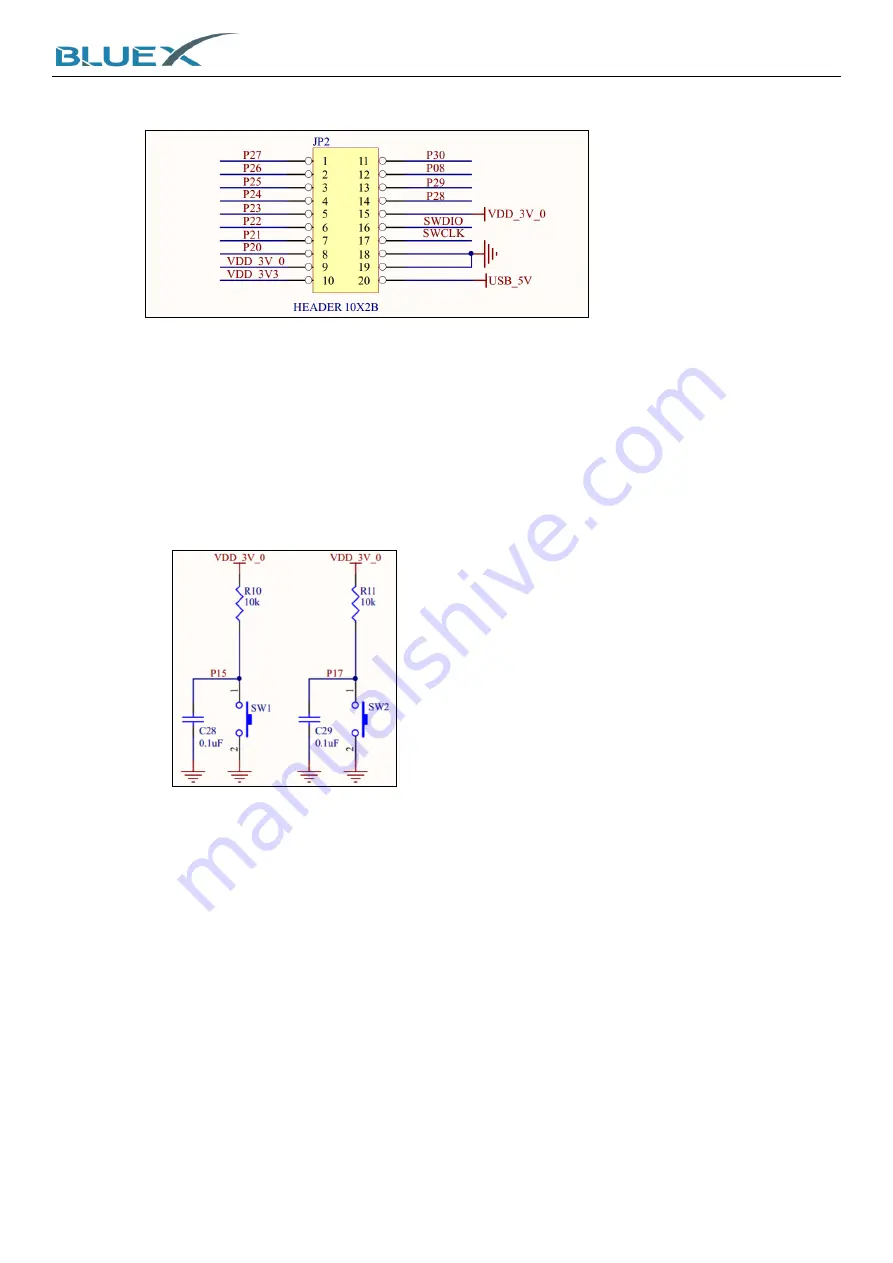
Power, IO, and SWD connect as below:
A.
Pin#15 and Pin#16 are RF01 SWD interface, using for debug and FW download.
(6)
SPI Flash
A.
CS#-P24, DO-P27, WP#-P28, HOLD#-P29, CLK-P25, DI-P26.
(7)
Power Supply 3.3V LDO.
(8)
P16/P23 DIP Switch
A.
P16 on the left, P23 on the right.
B.
Same as EVK of BX2400-dRF0xp-S1a. Please refer to #14 in paragraph 1.1 above.
(9)
Button
A.
IO connect as below:
(10)
Type-C USB
Connector
A.
USB 5V power input.
B.
It provides USB to convert to UART, and links to UART(P12/ P13) connector on module.
Summary of Contents for BX2400-dRF0xp-S1c
Page 15: ...System Installation of Evaluation Kit 15 5 Wait for installing 6 Click Finish to complete ...
Page 27: ...System Installation of Evaluation Kit 27 G RTT Log as below ...
Page 29: ...29 6 Appendix 6 1 Schematic of BX2400 dRF0xp S1c ...


