16
BA-101/3EN M53.XXXX
3 - Assembly
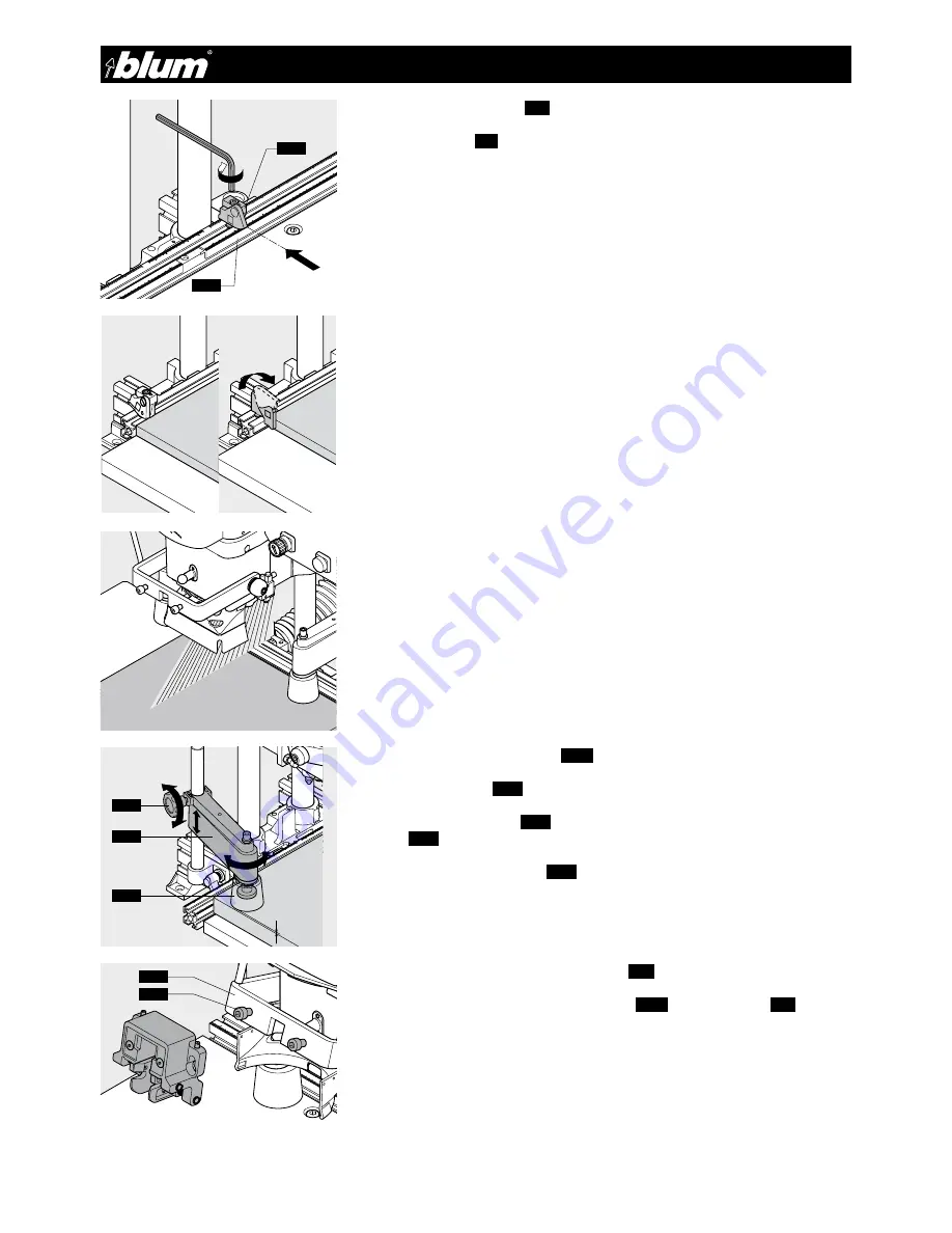
3.1.11) Setting swivel stops
(1.7)
Set the swivel stops
(1.7)
to the desired dimension and clamp.
3.1.12) Placing door on the work top and pushing up against the stop or marking
line
IMPORTANT:
Indicator edge is on the inside of the swivel part.
IMPORTANT:
The stop surface can be enlarged by swivelling the stop flap forward for
grooved work pieces and work pieces with radiuses (see picture).
3.1.13) Setting hold down clamps
(3.17)
to the material thickness
• Open clamping knob
(3.18)
.
• Set the hold down clamps
(3.17)
so that the distance between the door and the clamp
guard
(3.19)
is a max. x = 3 mm.
• Loosely tighten clamping knob
(3.18)
.
3.1.14) Attaching insertion ram to swing arm
(3.8)
• Place insertion ram on to the two fixing screws
(3.20)
on the swing arm
(3.8)
• Tighten the screws so that the insertion ram is secure.
L
1.2
1.7
!
!
X
3.18
3.17
3.19
3.8
3.20
Summary of Contents for MINIPRESS P
Page 1: ...BA 101 3EN M53 XXXX Please keep a copy of the operating instructions MINIPRESS P EN HO 051140 ...
Page 28: ...28 BA 101 3EN M53 XXXX 9 Diagrams 9 1 Electrical diagram 1x 230 V 50 Hz ...
Page 29: ...29 BA 101 3EN M53 XXXX 9 Diagrams 9 2 Electrical diagram 3x 230 V 50 Hz ...
Page 30: ...30 BA 101 3EN M53 XXXX 9 Diagrams 9 3 Electrical diagram 3x 400 V 50 Hz ...
Page 31: ...31 BA 101 3EN M53 XXXX 9 Diagrams 9 4 Pneumatic diagram 7 7 ...
Page 32: ...Printed in Austria IDNR 905 268 0 BA 101 3EN M53 XXXX DokId BAU0014224236 Idx 04 ...


