LAN-AD16f
2.4
Digital channels and counter
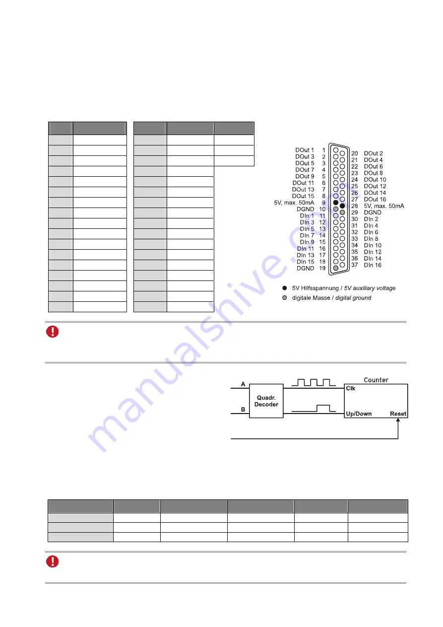
The LAN-AD16f features 16 digital inputs and outputs each (
low
: 0V..0.7V;
high
: 3.0V..5V). The digital
lines are hard-wired. A 19-bit counter (quadrature decoder) is additionally integrated allowing the connection
of an incremental encoder. The counter or incremental encoder and the external counter reset, if required, are
attached to the first digital input lines.
All lines are led to the 37-pin D-Sub female connector at the device front. The pin assignment is as follows:
Pin
LAN-AD16f
Pin
LAN-AD16f Counter
1 DOut
1
11
DIn 1
Signal A
20 DOut
2
30 DIn
2 Signal
B
2 DOut
3
12 DIn
3 Reset
21 DOut
4
31 DIn
4
3 DOut
5
13 DIn
5
22 DOut
6
32 DIn
6
4 DOut
7
14 DIn
7
23 DOut
8
33 DIn
8
5 DOut
9
15 DIn
9
24 DOut
10
34 DIn
10
6 DOut
11
16 DIn
11
25 DOut
12
35 DIn
12
7 DOut
13
17 DIn
13
26 DOut
14
36 DIn
14
8 DOut
15
18 DIn
15
27 DOut
16
37 DIn
16
9, 28 5V, max. 50mA
10, 19, 29
DGND
The digital inputs and outputs are protected by serial resistors. Input voltages beyond the permitted
voltage range of 0V..5V can damage the device.
The counter of the LAN-AD16f counts the num-
ber of incoming pulses (max. 8MHz) sampled at
the connection of signal A. If the maximum
counting range is reached, the counter will be re-
set to the minimum value of the counting range.
If the external counter reset is connected, the
counter can be reset at any time.
In comparison to a counter, the quadrature de-
coder considers the counting direction by decoding a second phase-shifted signal.
To activate the counting function, the respective digital lines of the LAN-AD16f must be programmed to
counter operation via software.
Function
Description Max. pulse frequ.
Connection
Dig. pins used Counting range
Counter count
Ç
8MHz
Signal
A
1
0..2
19
-1
Up/Down counter
count
ÇÈ
8MHz
Signal A, Signal B
2
2
18
.. 2
18
-1
Incremental encoder
count
ÇÈ
2MHz
Signal A, Signal B
2
2
18
.. 2
18
-1
Please see the manufacturer's documentation for details about connecting your incremental encoder.
Page 4


![Lambrecht power[cube] 30.95800.015000 Manual preview](http://thumbs.mh-extra.com/thumbs/lambrecht/power-cube-30-95800-015000/power-cube-30-95800-015000_manual_3388101-01.webp)


