USB-AD12f
Page 3
3
Digital inputs and outputs
The USB-AD12f features 4 digital inputs and outputs each
(
low
: 0V..0.7V;
high
: 3V..5V). In addition, the digital input 1
at pin 3 can be used as a 16-bit counter.
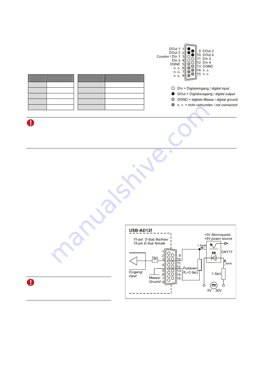
All connections are led to the 15-pin D-Sub female
connector on the back of the device. The pin assignment is as
follows:
Pin
USB-AD12f
Pin
USB-AD12f
1 DOut
1
3
DIn 1, counter
9 DOut
2
11 DIn
2
2 DOut
3
4 DIn
3
10 DOut
4
12 DIn
4
5, 13
DGND
6, 7, 8, 14, 15
n. c.
•
The digital lines are protected by 1k
Ω
resistors. If the input voltage is not within the permitted
voltage range of 0V..5V, the device may be damaged.
•
The digital ground (DGND) is connected with the PC ground.
4
Interfacing examples for the digital lines of the USB-AD12f
The following basic connection examples demonstrate the use of the digital inputs and outputs and the
connection of a counter to the USB-AD12f. The pin assignment of the 15-pin D-Sub female connector is
described in chapter 3.
4.1
Interfacing examples for digital inputs
The 3.9k
Ω
pull-down resistor sets the input to
low
if no voltage is applied there.
4.1.1
Connecting an optocoupler
Optocouplers provide optimum protection
at each input line. With them, it is possible
to connect higher voltages and to protect
the hardware from being destroyed.
In this regard, please also see application
examples of the optocoupler you use.
Optocoupler boards with 8 or 16 inputs
are available at bmcm.


