Additional Devices
First insert your wires in the correct location as per the labels. Check the
running of the gate each time you install a new device. This is so you do not
burn out
the system
accidentally
.
Connecting Exit Push Button:
Using speaker wire
Terminals 2 and 4 to activate open/stop/close
Connecting Keypad:
Using telecom wire
Keypad COM direct to gate open board terminal COM (#2)
Keypad NO direct to gate opener board terminal ONE (#4)
12v direct to gate opener board
+15v
(#1)
Keypad -GND direct to gate opener board
COM
(#2)
Connecting the IR beams:
Using telecom wire
Important Note:
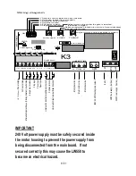
Terminals for eye beams are found in the bottom left corner
of the main control board. To install IR beams you will need power to both
IR beams. Connect one IR beam to the other IR beam -1 to -1 and +2 to +2.
Now connect the other IR beam direct to the main control board.
Connect -1 to -2 COM, +2 to +1 15v,
4
to 2 COM and
5
to 3 FSW
Make sure to remove the loop wire
Drive release mechanism:
The motor is
equipped
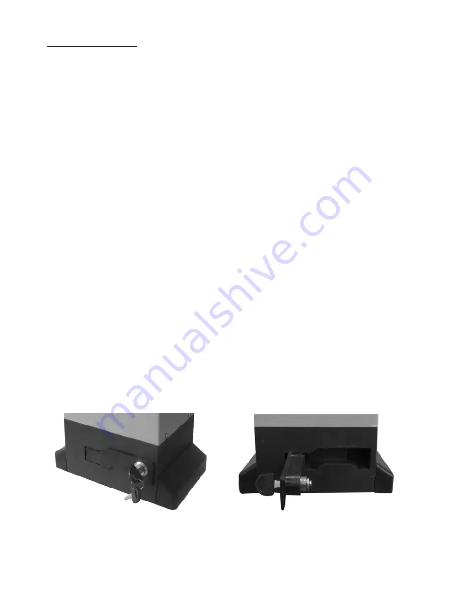
with a lockable release mechanism to enable the gate
to be operated manually due to a power cut. The release
mechanism is shown below with the clutch disengaging the link between the
cog wheel and rack. Insert your key into the lock and pull the clutch outwards.
Drive release mechanism and key
Clutch disengaged
8/1
1


