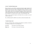
8.
Make sure that the stat, which is wired between terminals 1 & 2, is
closed and turn the man gas on to make the gas pressure switch and turn
the commissioning stop tap off. Switch the burner on, the burner should
run through its cycle and after the ignition spark goes out the burner
should lockout on flame failure on the burner control box.
9.
Open the commissioning tap and switch the burner on. The burner will
start on full air and the pilot will only open. When the pilot has
established then the pilot will go out and switch to the gas air ratio valve
the output of the burner will then be decided on the 0-10v dc signal.
When commissioning we would advise that you modulate the burner by
moving the low setting up to the same as the maximum setting and
unplug the 0-10v dc signal, then you can just turn the low speed down or
up to modulate burner. We would advise that you set the highest point
of the burner to the head pressure on the rating plate and adjust the air on
the inverter by high speed setting to get the correct combustion readings
of about between 0²: 4.0 & 5.0. After setting the top end then set the
bottom end of the burner by turning the low speed down. The burner fan
should slow down and the output should decrease, now set the burner to
the low head pressure and adjust the low setting to match the air for
combustion, the readings should be the same. For further information
see insert or inverter manual for inverter setting in this manual.
10.
Now plug the burner 0-10v dc back in and connect the 0-10v dc signal
back in. Now try the modulation, 0v dc will be 25% of the burner output
and 10v dc will be 100% burner output. Please note, you must check
emissions right throughout the range 0-10v and make sure gas and air
match each other. The emissions should be approx the same throughout.
11.
The high and low air pressure switch must be set on low speed. The low
air pressure switch is set by turning it up until it locks out and moving it
back 1.2mb on the pressure switch, then setting the high air pressure
switch to 1.2mb above the lockout pressure.
12.
The low gas pressure switch will be preset in the factory to 10mb.
13.
You are then required to check the strength of the flame sensing device
by removing the link on the burner which connects the flame probe to
the control box and put your multi-meter in series, which should give
you a reading in uA. The signal strength should be at least 70uA for
U.V. and 6uA on flame rectification.
30

