SFU-0302 SSE
M a n u a l
– 10–
BMR GmbH
2014-03-17
E
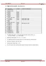
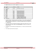
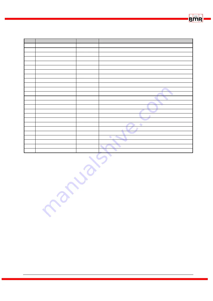
6.1 Digital and Analog I/Os
(D-Sub 25pin fem.)
Pin
Description
Direction
Function / User Message
1 Relay
Common
14 Relay Common
2
Relay 1
Output
15 Relay 2
Output
3
Relay 3
Output
16 Relay 4
Output
4
Relay 5
Output
17 Relay 6
Output
5
Relay 1 NO contact
Output
18 +24V/50mA
Output
auxiliary power supply
6
+24V/50mA
Output
auxiliary power supply
19 GND
7 GND
20 Relay 2 NO contact
Output
8
Hall Sensor
Output
RPM-Signal from DSP
21 Digital In 6
Input
9
Digital In 5
Input
22 Digital In 4
Input
10
Digital In 3
Input
23 Digital In 2
Input
11
Digital In 1
Input
24 Analogue In 1
Input
12
Analogue In 2
Input
25 Analogue Out 1
Output
13
Analogue Out 2
Output
•
The digital outputs (relays 1...6) are galvanically separated contacts (500V
Isolation
).
D.C.: 24V / 1000mA A.C.: 125V / 500mA
•
Digital input switching level: "0" 0...7V "1" 18...24V
•
The digital inputs require a high level of 24 V for correct function (PLC standard level).
•
Hall sensor output level: 0-24V (24V level.)
•
Analogue input voltage range: 0...10V
•
The +24V output can be used as a power supply for this type of electronic spindle interface.
Summary of Contents for SFU-0302-SSE
Page 1: ...Frequency Converter SFU 0302 SSE ...
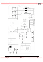
Page 5: ...SFU 0302 SSE M a n u a l 5 BMR GmbH 2014 03 17 E 3 Block Diagram ...
Page 6: ...SFU 0302 SSE M a n u a l 6 BMR GmbH 2014 03 17 E ...
Page 28: ...SFU 0302 SSE M a n u a l 28 BMR GmbH 2014 03 17 E 13 Mechanics Views Dimensions ...
Page 29: ...SFU 0302 SSE M a n u a l 29 BMR GmbH 2014 03 17 E this page is left intentionally left blank ...


