background image

SFU-0302 SSE 

M a n u a l 

– 7– 


BMR GmbH 

2014-03-17 

E   


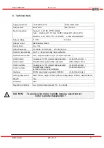
4. Technical Data 


Supply connection 

 115V, 60Hz, 1PH    

230V, 50Hz, 1PH    

Output power 

Max 2 kVA 

Max 3,6 kVA 

Motor connection 

7-pole: U, V, W, PE, 2*PTC, SGND  
Type:    Amphenol C16-1 (fem. 6+PE) / Binder 693  (fem. 6+PE) 
 
8-pole: U, V, W, 2*PE, PTC, FP, SGND       screw terminals 4mm

Output voltage 

3* 115V 

3* 230V 

Output current 

Electronically limited  

Over-current max. 

10s 

Output frequency 

AC: 3kHz / 180.000 rpm     DC: 60.000 rpm 

Spindle characteristics 

max 16,  stored internally, freely definable 

Spindle sensor inputs 

PTC, magneto-resistor, logic   (D-Sub 15-pin fem. ) 

Control inputs 

2 analogue: 0-10V, galvanically separated :      (D-Sub 25-pin fem. ) 

Control inputs 

6 digital: 0-24V, galvanically separated:            (D-Sub 25-pin fem. ) 

Control outputs 

2 analogue: 0-10V, galvanically separated        (D-Sub 25-pin fem. ) 

Control outputs 

6 digital: relay outputs,                                       (D-Sub 25-pin fem. ) 
24VDC/1000mA, 125VAC/500mA  

Interface      

RS232 galvanically separated, 9600Bd             (D-Sub 9-pin male ) 

Housing dimensions 

width 130mm, height: 320mm (with mounting straps: 380mm), depth: 262mm 

Weight 7 

kg 

Protection IP20 

Operating conditions 

max. ambient temperature 40°C, no humidity 


CAUTION:      To avoid severe motor / spindle damage, select correct 
                                      motor / spindle characteristic ! 

Summary of Contents for SFU-0302-SSE

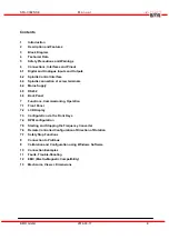
Page 1: ...Frequency Converter SFU 0302 SSE ...

Page 2: ...erminals 6 4 Mains Supply 6 5 RS232 6 6 Back Panel 7 Functions Commissioning Operation 7 1 Front Panel 7 2 LCD Display 7 3 Configuration via the Front Keys 7 4 RPM configuration 7 5 Starting and Stopping the Frequency Converter 7 6 Remote Controlled Configuration of Direction of Rotation 7 7 Safety Stop Functions 8 Connection to Profibus 9 Calibration and Configuration using Windows Software 10 Co...

Page 3: ...maller In the aforementioned applications three phase a c motors are operated using special control gear frequency converters These frequency converters convert the fixed 50 Hz network into a 3 phase network with variable frequency and voltage This greatly reduces the start up problems and the high starting currents that are inevitable when high capacity three phase a c motors are connected to a f...

Page 4: ...power failure or Emergency Stop Integrated braking resistor for reduced external wiring Transparency The user is continuously informed of the status of the frequency converter and the motor spindle by means of a 4 column plain text display on the front panel Control The frequency converter can be manually controlled and calibrated as required using 6 keys on the front panel Individual adaptation t...

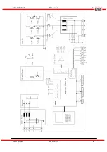
Page 5: ...SFU 0302 SSE M a n u a l 5 BMR GmbH 2014 03 17 E 3 Block Diagram ...

Page 6: ...SFU 0302 SSE M a n u a l 6 BMR GmbH 2014 03 17 E ...

Page 7: ...ble Spindle sensor inputs PTC magneto resistor logic D Sub 15 pin fem Control inputs 2 analogue 0 10V galvanically separated D Sub 25 pin fem Control inputs 6 digital 0 24V galvanically separated D Sub 25 pin fem Control outputs 2 analogue 0 10V galvanically separated D Sub 25 pin fem Control outputs 6 digital relay outputs D Sub 25 pin fem 24VDC 1000mA 125VAC 500mA Interface RS232 galvanically se...

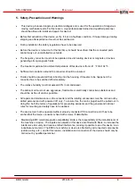
Page 8: ...converter has to be switched off immediately The relative humidity must not exceed 90 not condensed The ambient air must not use aggressive flammable or electrically conductive substances and should be as free of dust as possible All repairs and maintenance on the converter and the relating accessories must be carried out by skilled personal and with powered off only To ensure this the mains plug ...

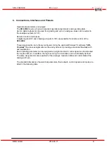
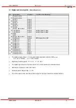
Page 9: ... of the SFU 0302 These assignments can be freely configured Using the optional Windows PC software SFU Terminal the above assignments can be easily achieved providing exceptional flexibility with each application Each operating parameter can be assigned as a signal and each control signal can be allocated the required I O pin In addition the logic level high or low active can be individually defin...

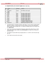
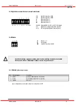
Page 10: ...M Signal from DSP 21 Digital In 6 Input 9 Digital In 5 Input 22 Digital In 4 Input 10 Digital In 3 Input 23 Digital In 2 Input 11 Digital In 1 Input 24 Analogue In 1 Input 12 Analogue In 2 Input 25 Analogue Out 1 Output 13 Analogue Out 2 Output The digital outputs relays 1 6 are galvanically separated contacts 500VIsolation D C 24V 1000mA A C 125V 500mA Digital input switching level 0 0 7V 1 18 24...

Page 11: ...nal from Spindle 15 PTC Input Temperature Signal from Spindle 8 Hall sensor Input RPM Signal from Spindle to DSP The spindle interface is completely isolated by optocouplers It can be used for automatic spindle detection if enabled To set a high level to one bit a simple connection to the spindle GND is made An open contact equals low level The direction of high low active can be changed in the fo...

Page 12: ... Spindle speed PTC PTC Signal Spindle Temperature 6 4 Mains Control cables supply cables and motor cables must be isolated from each other Shielded cables are to be preferred 6 3 RS232 D Sub 9pin male Pin Description Function 2 RxD receive data data to converter 3 TxD send data data from converter 5 GND Ground use a standard zero modem cable for connection to PC PE PE U V PTC FP SGND W 1 3 4 5 6 2...

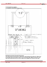
Page 13: ...SFU 0302 SSE M a n u a l 13 BMR GmbH 2014 03 17 E 6 5 Screw Terminals figure 1 Mains Spindle screw terminals ...

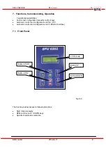
Page 14: ...nually via front keys Automatic control and configuration via PLC IPC Automatic control and configuration via PC RS232 interface 7 1 Front Panel figure 2 The front keys allow access to following functions Start Stop manually RPM control via UP DOWN keys Spindle characteristic selection Button UP Button DOWN LCD 4 rows Button START Button STOP ...

Page 15: ...d of converter O v e r t e m p e r a t u r e Error overtempertature of the spindle O v e r t e m p S p i n d l e Error overtemperature of converter and spindle O v e r t e m p c n v s p Error overvoltage O v e r v o l t a g e s t o p Error undervoltage U n d e r v o l t o u t Error undervoltage Stop U n d e r v o l t s t o p Error powerstage disabled P W R s t a d i s a b l e d Error shutdown enab...

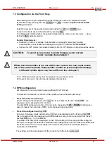
Page 16: ...ve different line voltages The LCD shows all relevant system messages for speed load or errors In the event of an error the error type is displayed in plain text 7 4 RPM configuration all references to menues relate to setup software SFU Terminal The preset of revolutions per minute of the spindle can be achieved by two ways Preset manually via panel keys In form Analogue Inputs option button 0V h...

Page 17: ...alogue inputs is selected and a valid signal at the digital input Start Stop is present Additionally a scaling has to be selected from list box duty RPM of analogue value to RPM Remotely via the RS232 serial interface from a PC or PLC The speed pre selected from the panel is taken as the required speed in this instance Speed can be altered via commands from the RS232 interface The RS232 interface ...

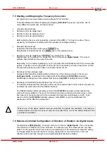
Page 18: ...essed by delays button Safety stop by overload and time delay exceeded determined by maximum current and voltage in the spindle diagram and the form delays accessed by delays button Immediate safety stop by over current of the converter Safety stop by emergency stop through digital input shutdown in form digital inputs The following stopping methods shut off the power stage and the spindle will sl...

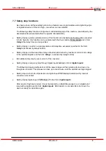
Page 19: ...for example into Siemens S7 are available under Support Download BMR GSD The setup of address of station is carried out either Online with the help of SFU Terminal and the listbox Profibus Address or Offline Pressing Start and Stop key simultaneously during PowerOn will show a selection menu The address can be changed in the range of 0 126 with the Up Down keys Storing and returning to operating m...

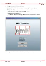
Page 20: ...ides the possibility of user friendly data display and calibration implemented as follows 1 Start up frequency converter and connect via RS232 interface 2 Start up program SFUTerminal exe The interface is then configured automatically A connected frequency converter is detected and all data transfer parameters are synchronised The description can be found in the help menu and manual of SFU Termina...

Page 21: ...ting behaviour with released analogue input The motor will start when dig start is high and the input voltage of the duty rpm is higher than the min rpm given in the field min rpm in the according spindle diagram It will stop when either the dig start pin wents low or the voltage at the analogue pin is lower than the given ...

Page 22: ...SFU 0302 SSE M a n u a l 22 BMR GmbH 2014 03 17 E min rpm Eg When 10V are applied at the analogue input 1 and the dig start is high the motor will start and accelerate up to ist max rpm ...

Page 23: ...s or with SFU Terminal After power on the converter indicates Not Ready and Error Short circuit detection of the out put has tripped Check if the spindle is blocked Check if there is a short circuit within the spindle Check if there is a Ground fault at least one prong of the spindle cable is connected with PE Check if there is a short circuit within the spindle cable Error Description Cause Fixin...

Page 24: ...erminal Start with push buttons not possible Start button deactivated Enable Start button by un checking the checkbox Block Start Button An input is assigned with the function Emergency Stop and configured as Low Active This is default state on delivery For unlocking a signal of HI 24V is required at this input Deactivate this function or setup as High Active The evaluation of the temperature sens...

Page 25: ...xcess temperature Let it cool down Check if the characteristic matches with the spindle PTC in the spindle is defective change spindle The error message Spindle not ready is indicated The PTC wires within the spindle cable are defective exchange cable or fix the connection Start via Analogue input is activated Deactivate Start via analogue input Manual Analogue Inputs and activate Digital Start St...

Page 26: ...ielded Exchange spindle cable for verification test exchange spindle Spindle cable is defective Check the 3 spindle phase wires Error Without Spindle Cable is displayed Spindle cable too long With activated spindle test a test current is send via spindle cable to the spindle by applying a voltage at output lines In case that this current is too low or a wrong spindle characteristic selected it doe...

Page 27: ...njunction with the frequency converter should be as short as possible and have as large a cross section as possible Control devices used with the frequency converter PLC CNC IPC should be connected to a common earth earth terminal bar For mechanical installation use serrated lock washers to guarantee good electrical contact with the housing All connections both to and from the frequency converter ...

Page 28: ...SFU 0302 SSE M a n u a l 28 BMR GmbH 2014 03 17 E 13 Mechanics Views Dimensions ...

Page 29: ...SFU 0302 SSE M a n u a l 29 BMR GmbH 2014 03 17 E this page is left intentionally left blank ...

Page 30: ... u a l 30 BMR GmbH 2014 03 17 E Walpersdorfer Straße 38 D 91126 Schwabach Germany Tel 49 0 9122 63148 0 Fax 49 0 9122 63148 29 e mail Info bmr gmbh de Internet www bmr gmbh de Subject to technical alterations 2014 03 24 ...

Reviews: