Optional versions
12
alpha E32 and alpha E63 12.1
171
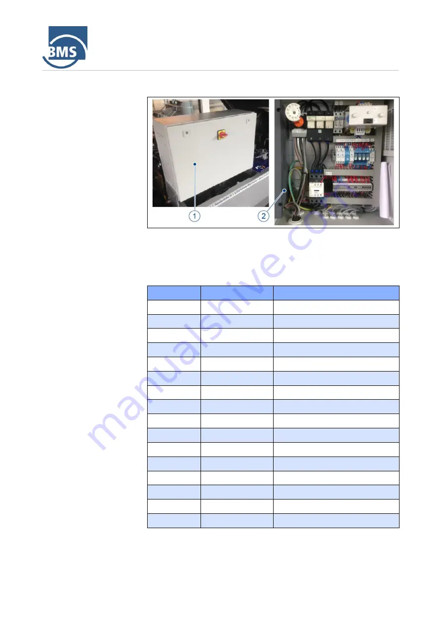
12.1.2 Control cabinet
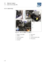
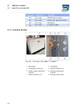
Figure 67: Control cabinet
alpha
E32
and
alpha
E63
1 Control cabinet
2 Interior view control cabinet
Equipment designation
Designation
Component
Allocation
Q1
Main switch
F1
Main fuse
F2
Fuse
Transformer
F3
Fuse
Transformer
F4
Fuse
Transformer 12 V DC
F5
Fuse
Start
F6
Fuse
Lubrication system
F7
Fuse
Headlights
F8
Fuse
Motor control
F9
Fuse
Machine control
KM1
Main contactor
K1
Relay
Vessel safety switch
K2
Relay
Compressor motor start
K3
Relay
Safety chain
K4
Relay
Sponsorship
K5
Relay
Release radio etc.
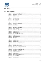
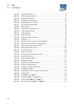
Summary of Contents for alpha CR
Page 6: ...Contents ...
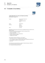
Page 180: ...14 Appendix 14 1 Declaration of conformity 180 14 1 Declaration of conformity ...
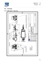
Page 181: ...Appendix 14 Drawings 14 2 181 14 2 Drawings 14 2 1 BMS alpha CR standard ...
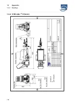
Page 182: ...14 Appendix 14 2 Drawings 182 14 2 2 BMS alpha CR B feeder ...
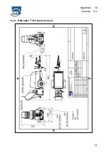
Page 183: ...Appendix 14 Drawings 14 2 183 14 2 3 BMS alpha CR B S feeder scraper ...
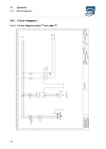
Page 185: ...Appendix 14 Circuit diagrams 14 3 185 ...
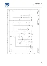
Page 186: ...14 Appendix 14 3 Circuit diagrams 186 ...


